Wiring harness routing & packaging Rules Week 3 Challenge
1. DEFINING P CLAMP
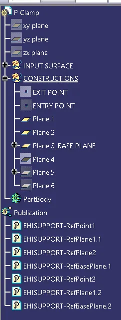
GENERATING ENTRY, EXIT POINTS AND PLAINS
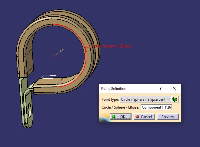
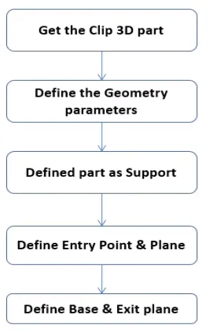
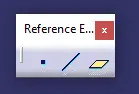
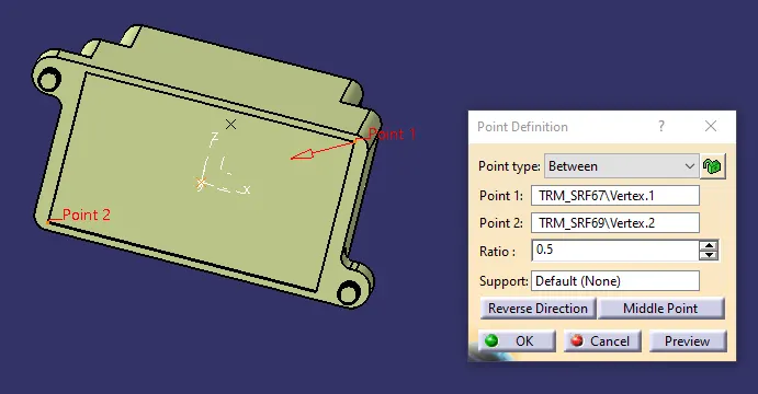
Here the point is generated as shown above for one side [Entry]. Same method is used to generate point on the other side [Exit] and planes are generated on both the points including Base plane as shown below.
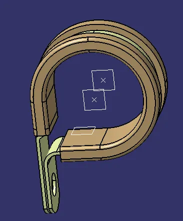
DEFINING P-CLAMP AS SUPPORT
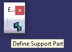
"Define Support Part" Icon is used to define the P-clamp as support. This icon is available in Electrical Part Design Workbench.[EPD]
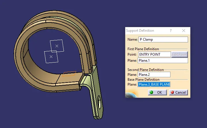
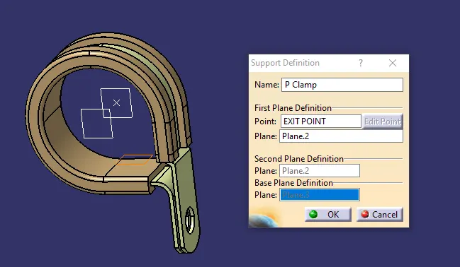
2.
The point generated on both sides using Between option available in Part Workbench.
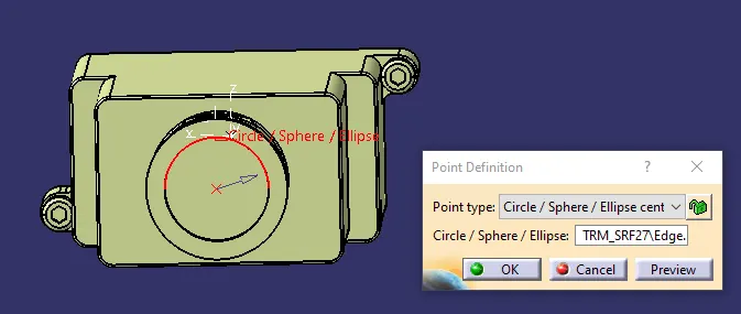
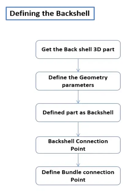
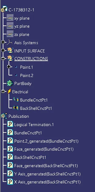
DEFINING BUNDLE AND BACKSHELL CONNECTION POINTS IN EPD WORKBENCH
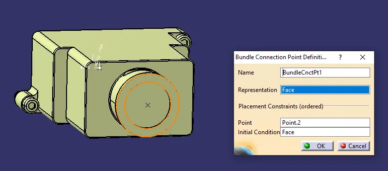
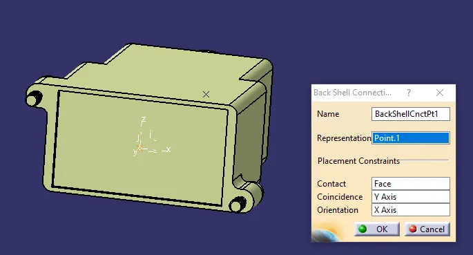
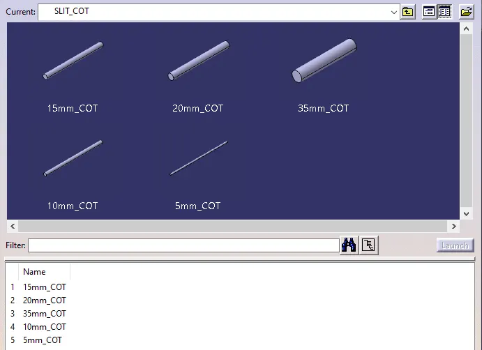
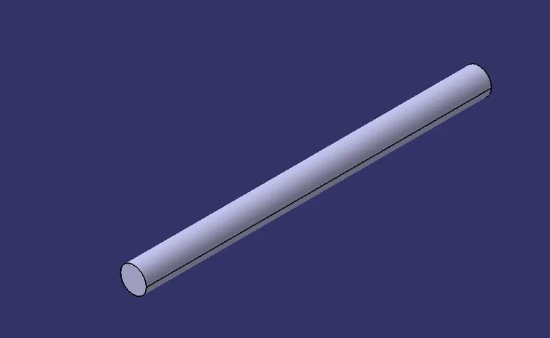
3. Corrugated tubes under “Slit COT” family Catalogue.
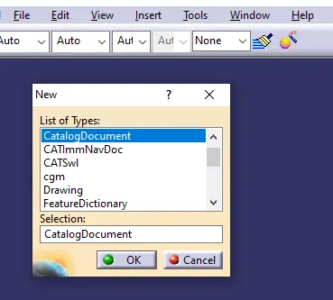
 and saved in the respective folder we want.
Creating respective parts in Electrical Part Design Workbench [EPD].
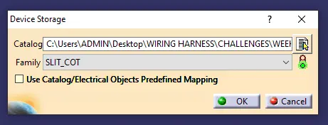
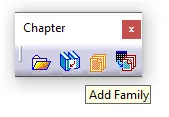
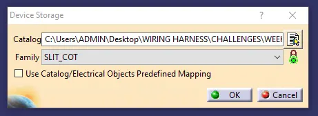
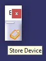 This Icon is used to store the component we needed in the respective family as shown below
In Electrical Assembly Design [EAD] the catalog browser icon selected as shown below.