Wiring harness design in CATIA V5 - 3D modeling Week 7 Challenge
OBJECTIVE:
- To flatten the wire harness assembly completed in the week 4 assignment.
- To orient the wire bundle as shown in the layout.
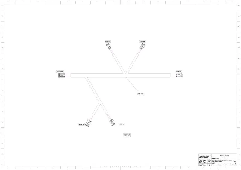
- Place the flattened view on a drawing sheet.
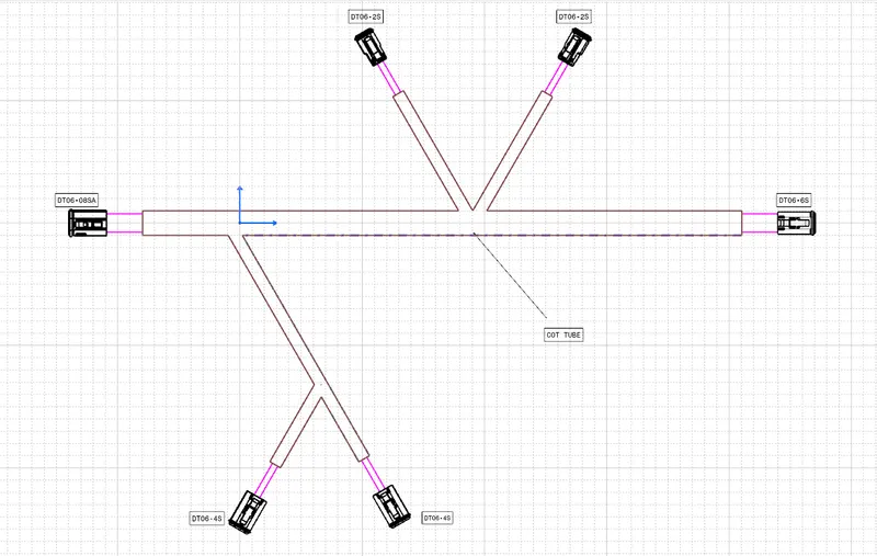
- Ensure bundles with protective coverings has different visuals on the drawing view.
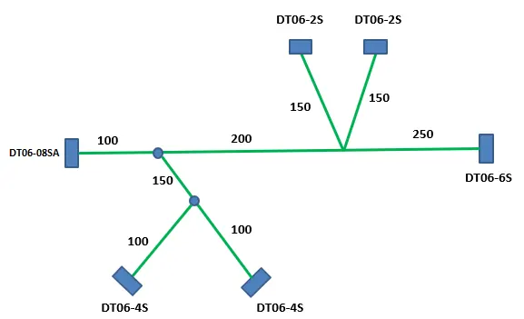
SOLUTION METHODOLOGY:
Step - 1:
- Create a product file, navigate to the Electrical Harness Flattening for wire harness flattening option, and save it in the same location where the wire harness or routing assembly is stored.
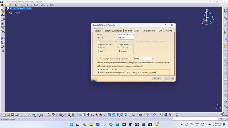
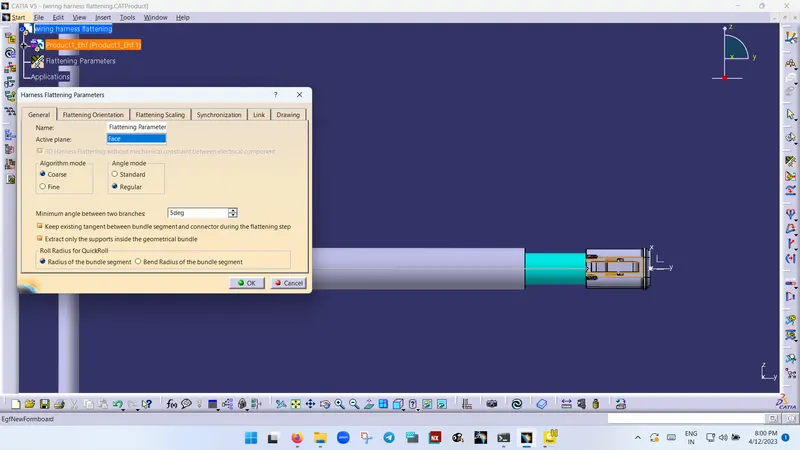
- Define the 'Harness flattening parameters' in order to flatten the required wire harness assembly.
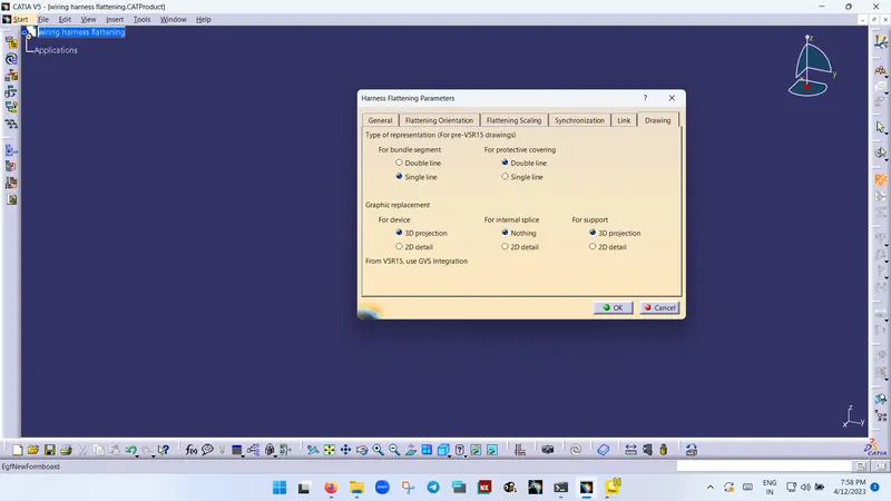
- While defining the harness flattening parameters in the drawing menu, a single line is selected for the bundle segment, and a double line is selected for protective coverings to differentiate between the wire bundle and cot tubes in drafting.
Step - 2:
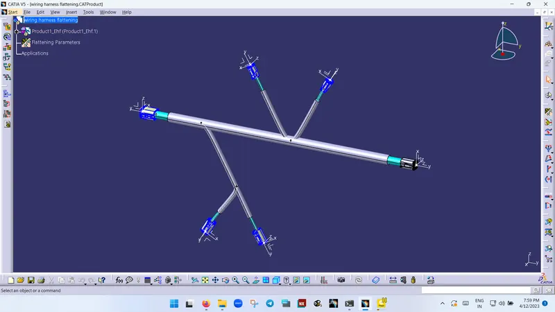
- Select the 'Extract' option from the Electrical Harness flattening workbench and select the Geometric bundle product in the wire harness assembly product file.
- Then wire harness assembly is imported to the Wire flattening product file with the 'EHF' extension added to the geometric bundle assembly name.
Step - 3:
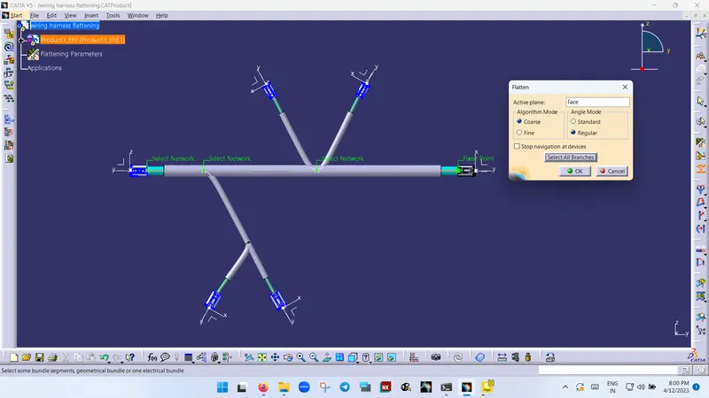
- Select the 'Flatten' option to flatten the wire harness assembly.
- Then select the active plane, select any one branch, and select the 'select all branches'.
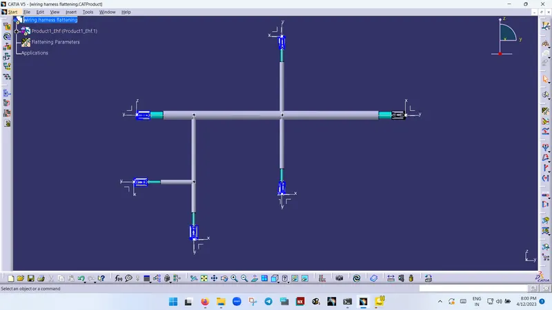
- If there is no discontinuity in the bundle segment then all the branches will be selected and by pressing 'ok' the wire harness assembly will be flattened.
Step - 4:
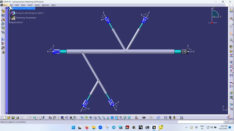
- Use 'Rotate' and other commands to rotate the branches and bring them in the proper orientation as per the given layout.
Step - 5:
- Save the product file using the 'Save management' option so that all the related product files and part files are stored in a single directory.
DRAFTING:
Step - 1:
- Create a new drawing file and save the file in the same location.
Step - 2:
- Insert the title block template and fill up the required details.
Step - 3:
- Add the front view of the harness assembly by selecting any one of the flat faces of the connector and orienting the view as per the requirement.
Step - 4:
- Go to the properties of the view and select the '3D Wireframe' and ' Is always visible' options in order to see properly the Wire bundle, connectors, and protective coverings.
Step - 5:
- Show and name all the parts used in the wire harness assembly in form of a table.
CONCLUSION:
From the above assignment, we learned how to flatten a given wire harness assembly and how to place the flattened view on a drawing sheet and show all its components.