Week 8 - Challenge 4 - Bumper
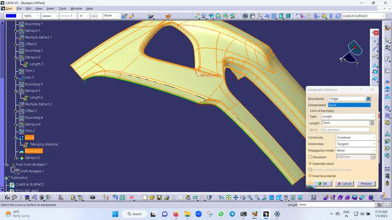
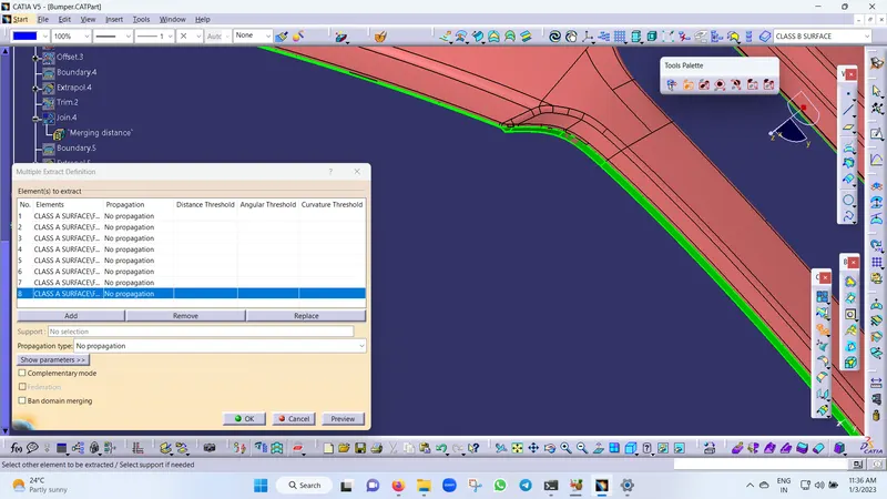
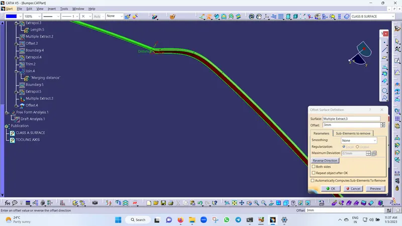
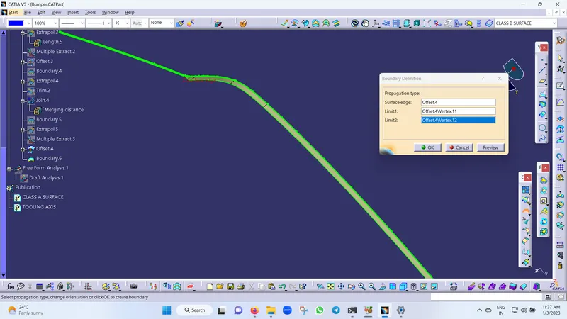
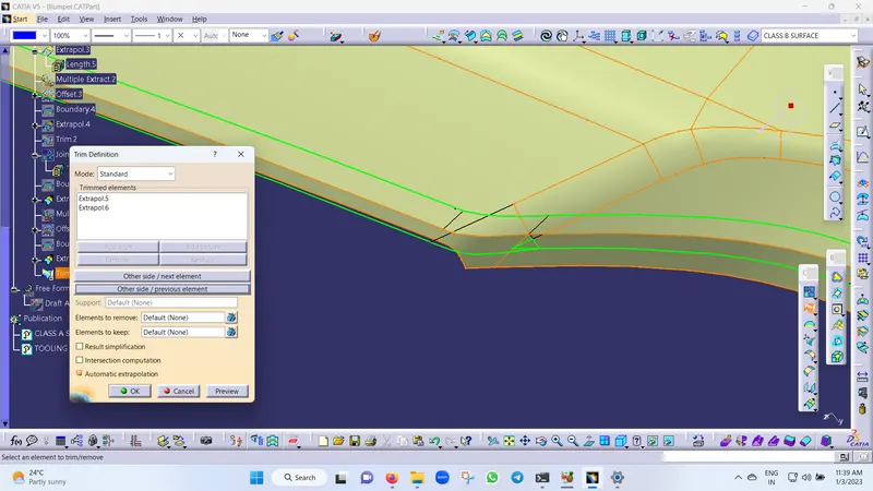
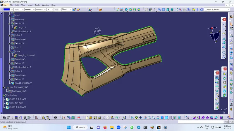
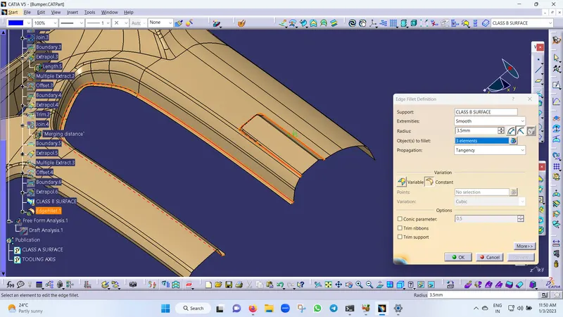
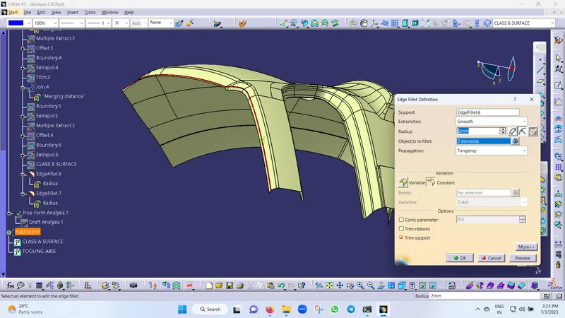
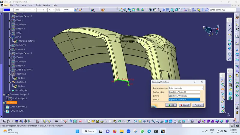
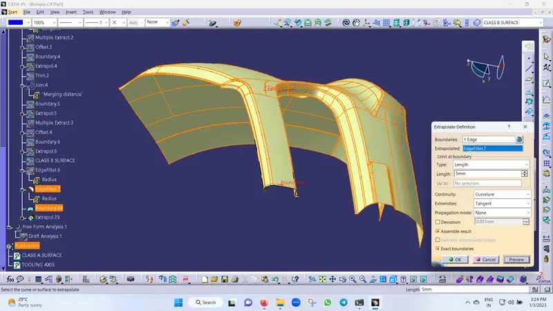
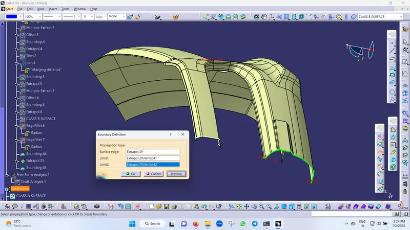
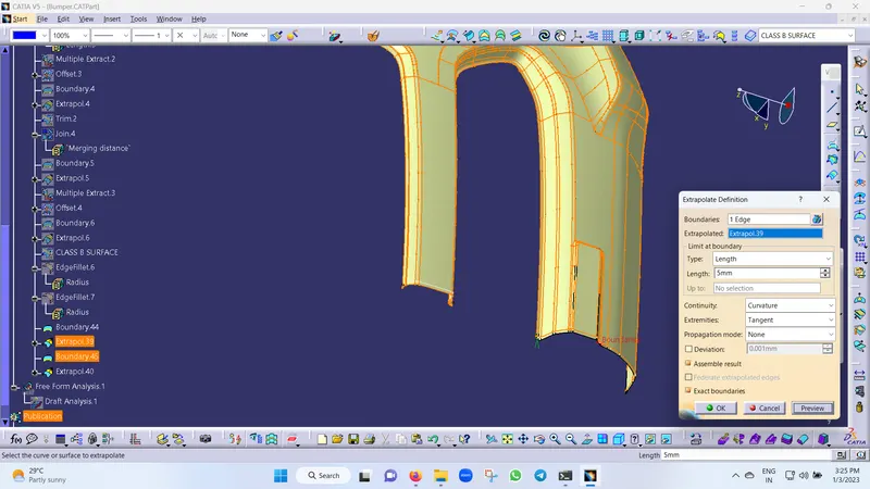
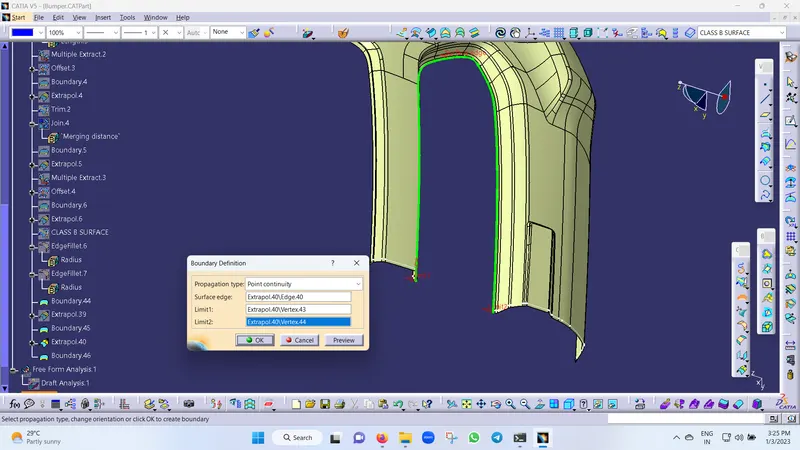
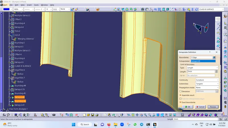
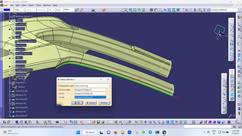
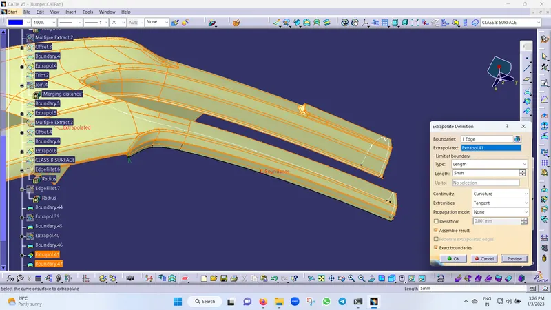
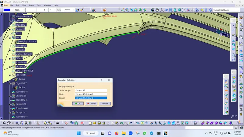
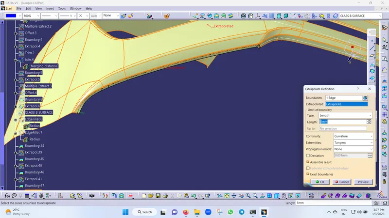
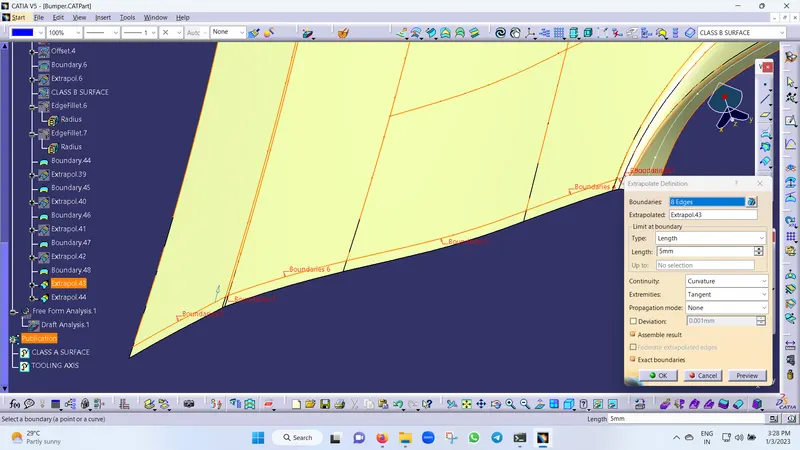
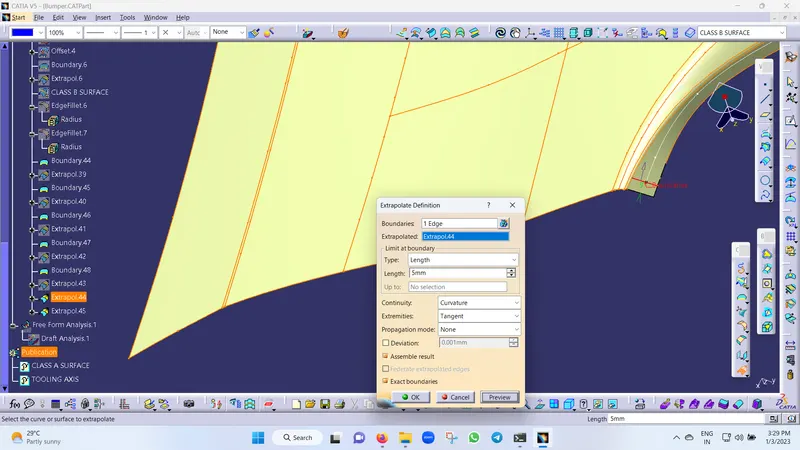
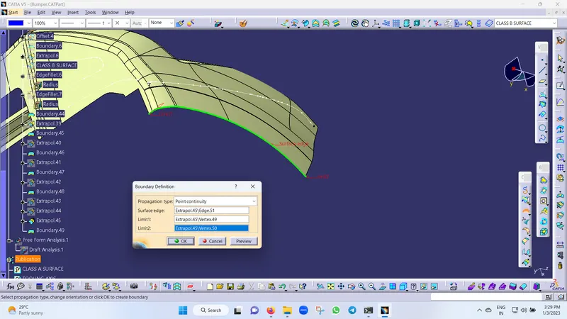
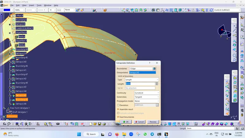
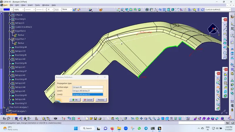
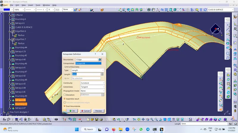
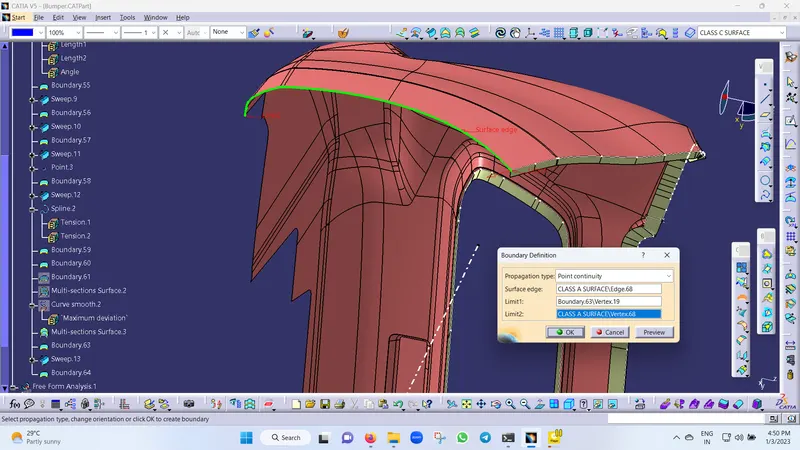
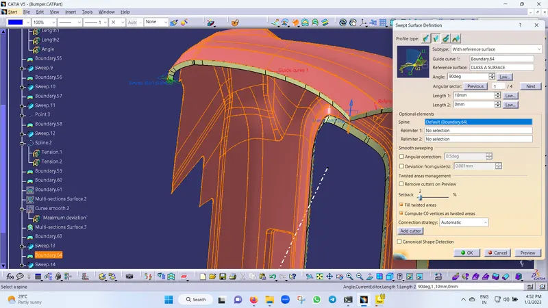
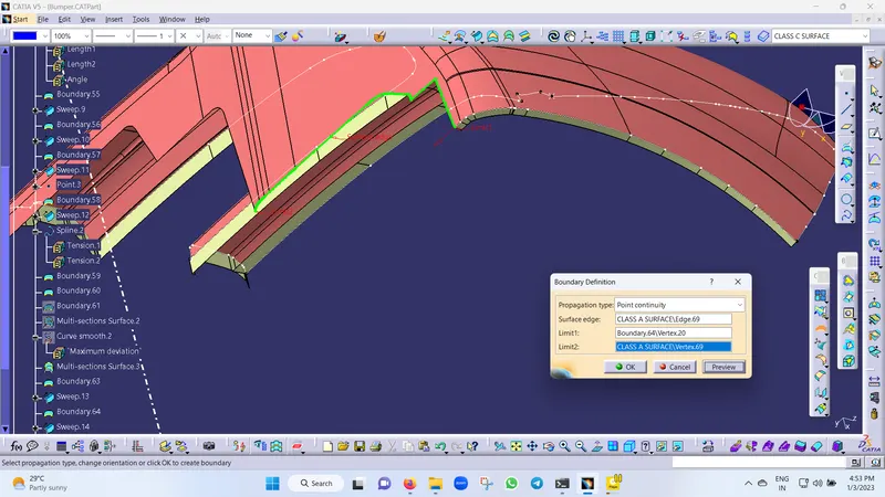
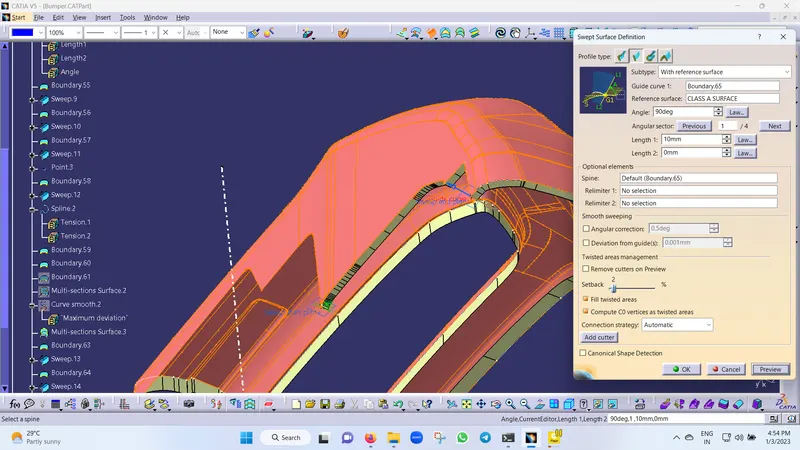
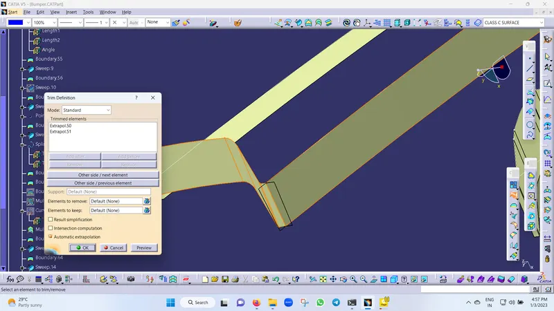
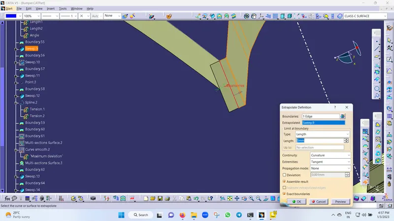
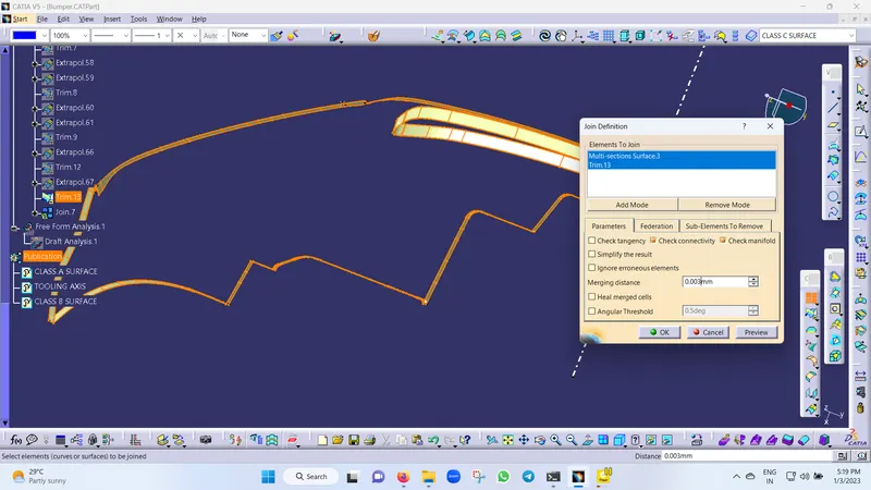
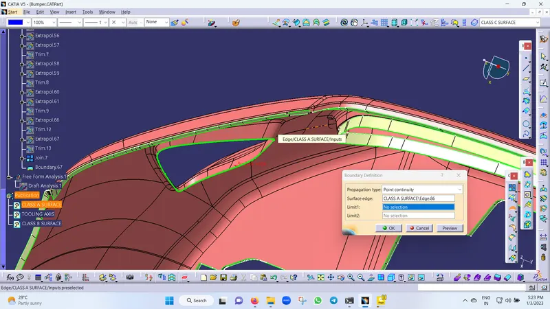
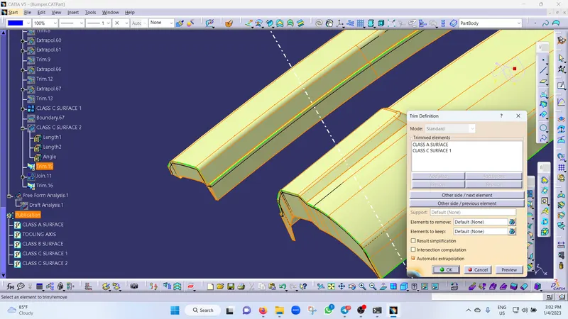
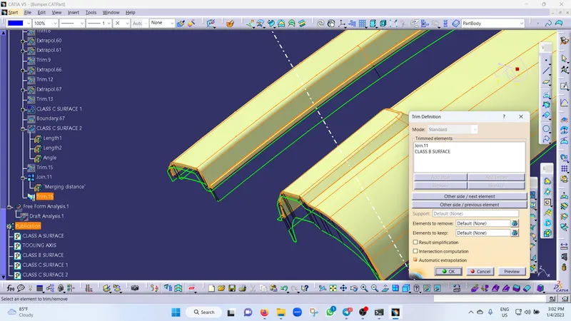
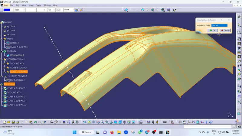
SCREENSHOTS:
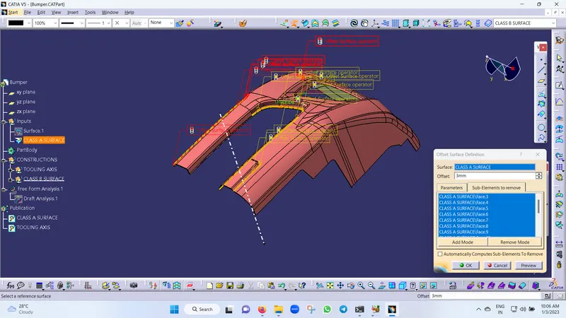
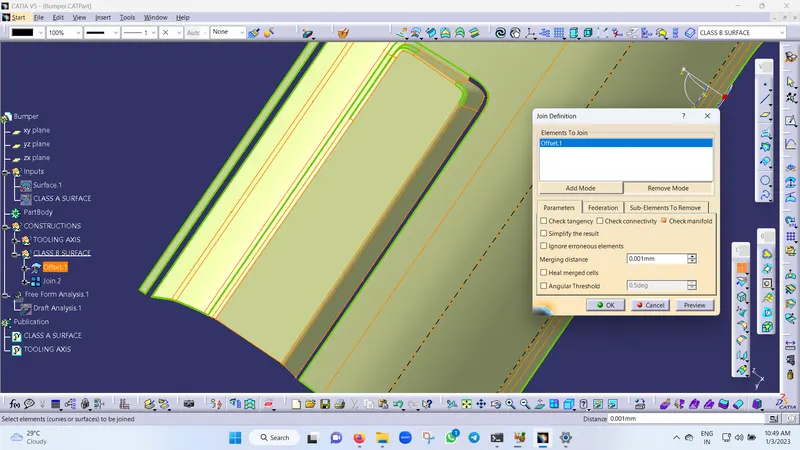
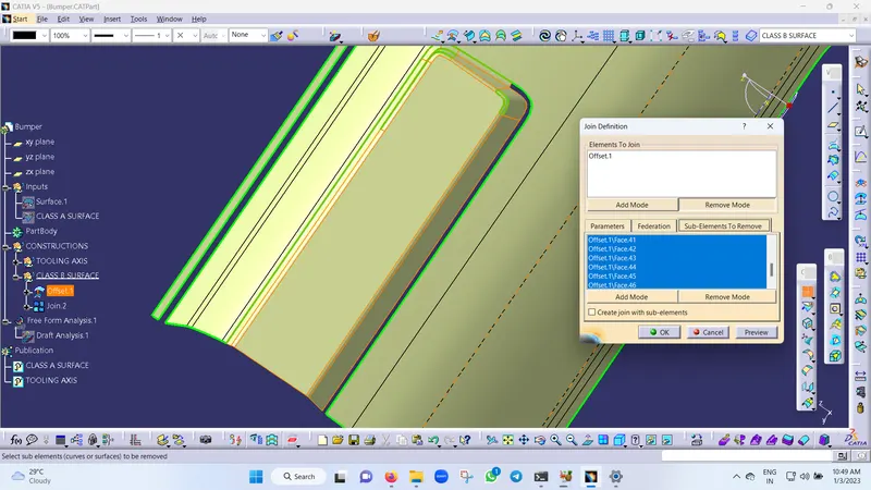
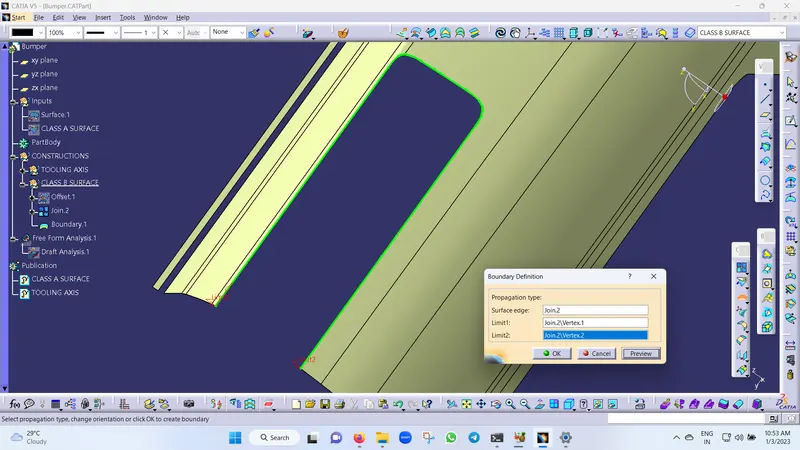
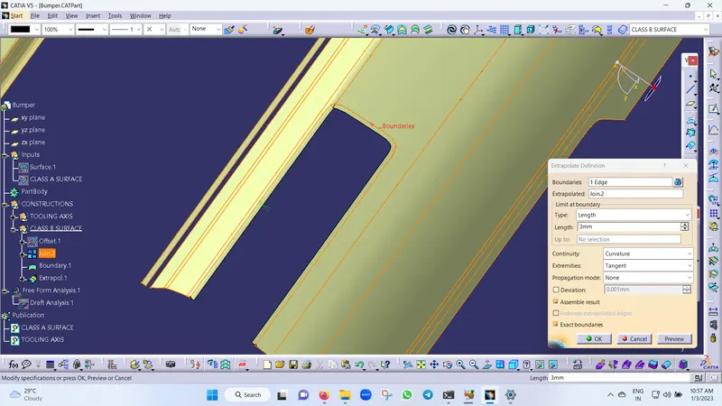
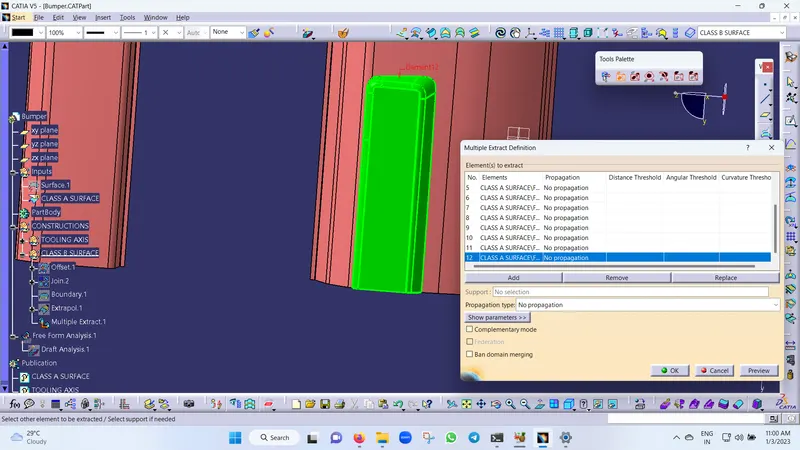
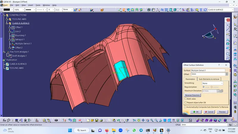
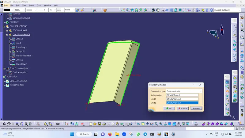
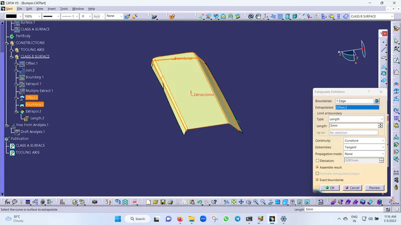
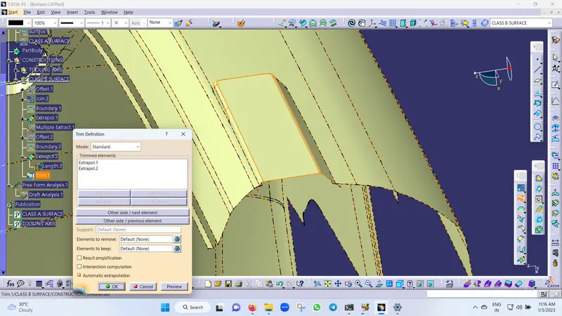
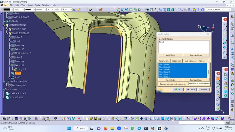
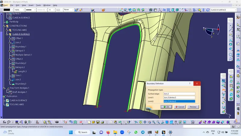
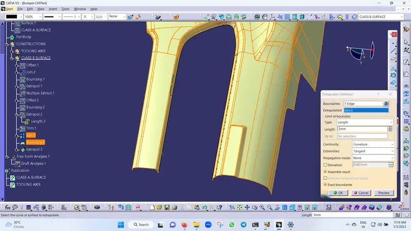
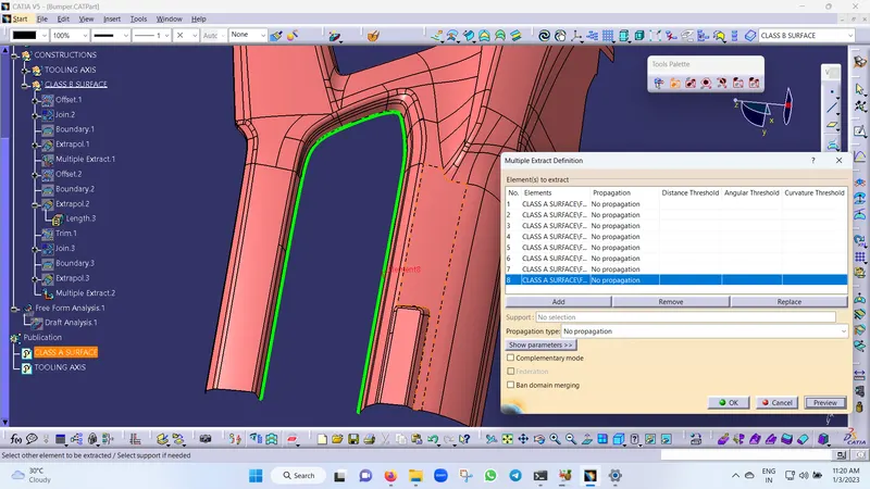
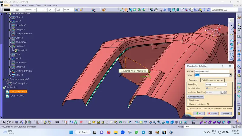
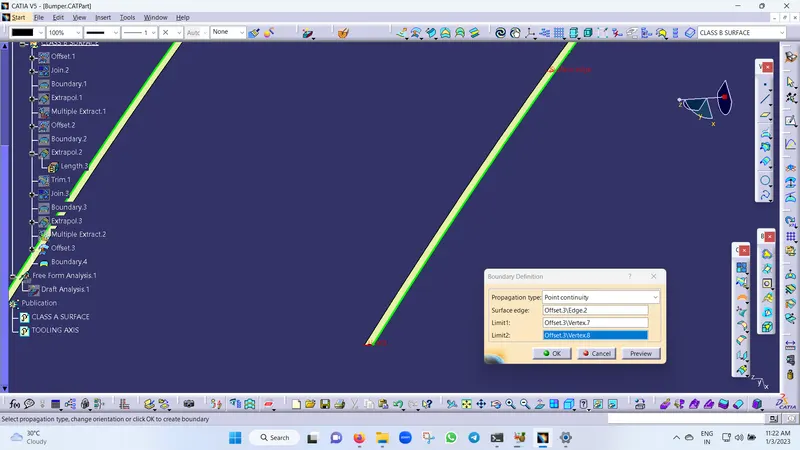
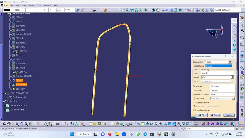
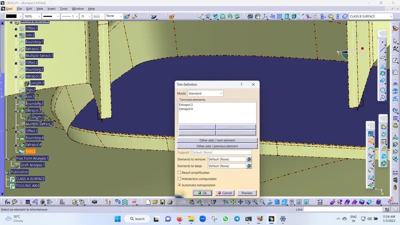
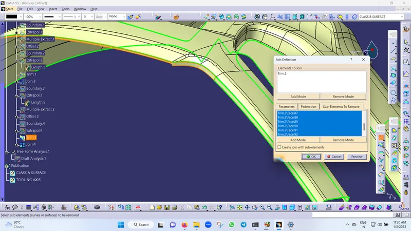
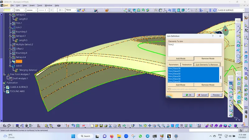
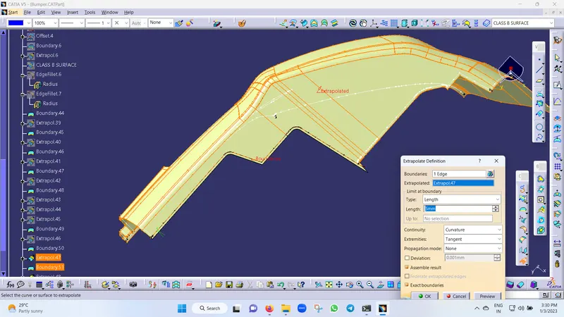
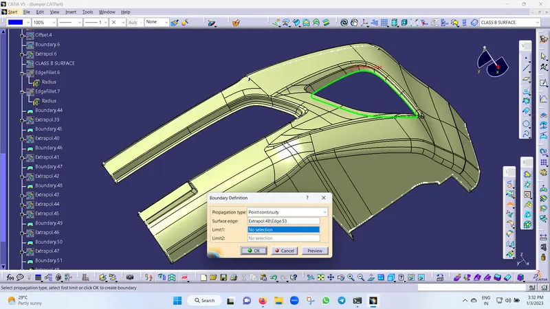
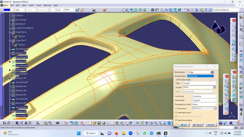
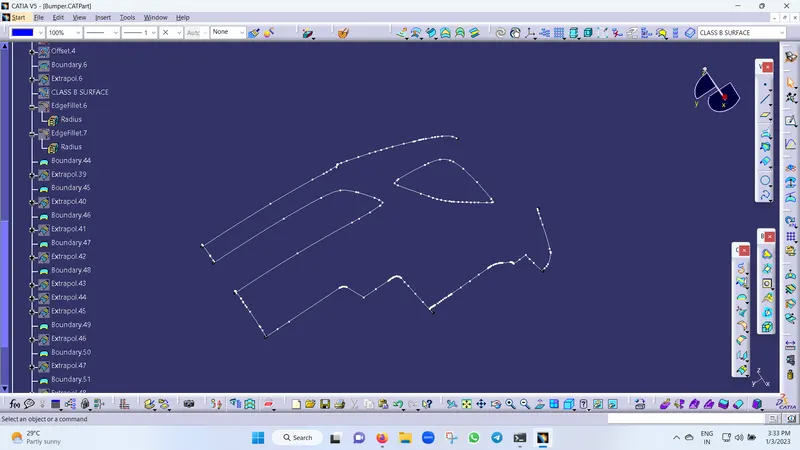
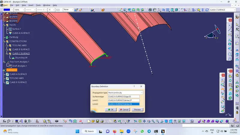
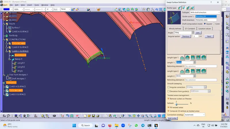
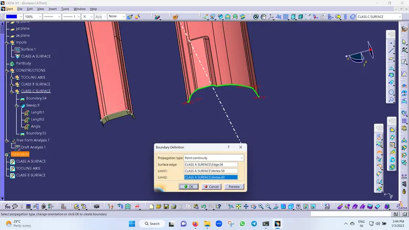
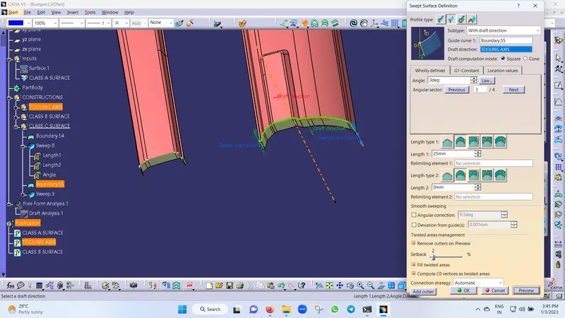
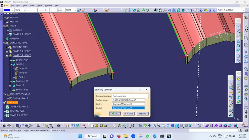
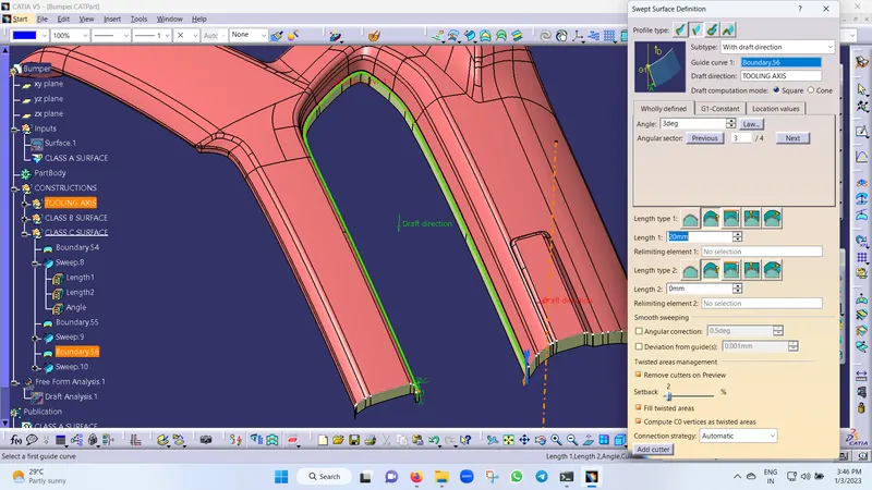
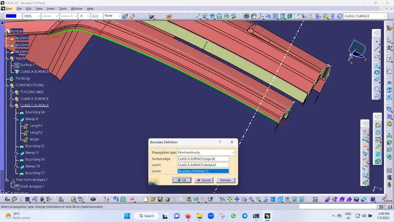
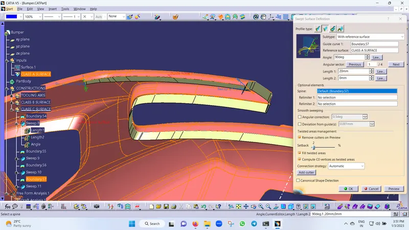
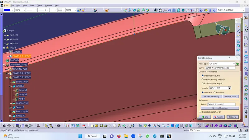
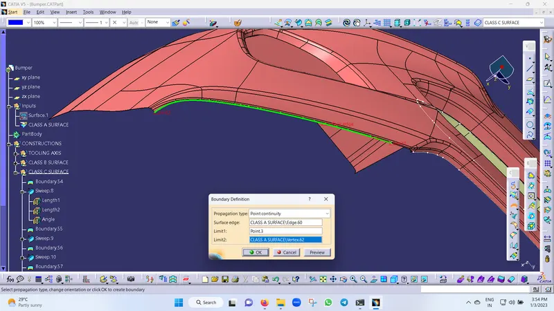
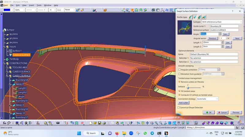
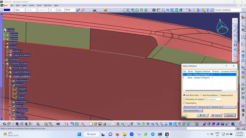
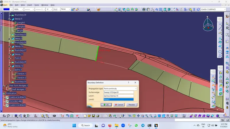
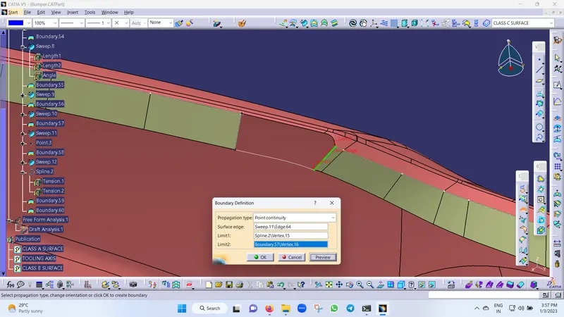
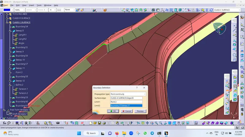
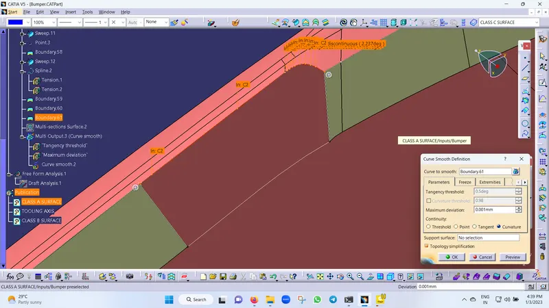
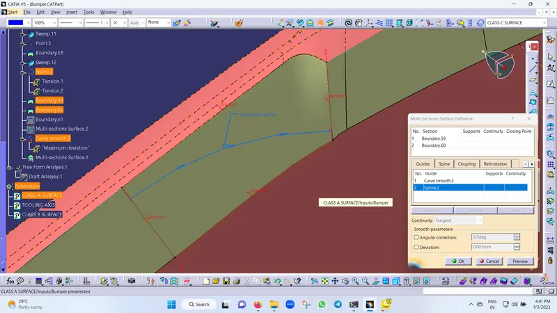
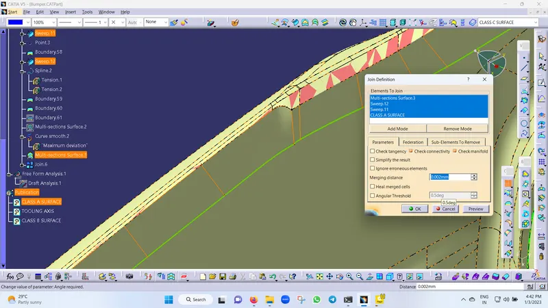
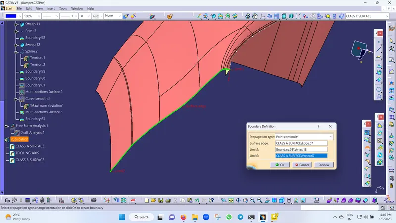
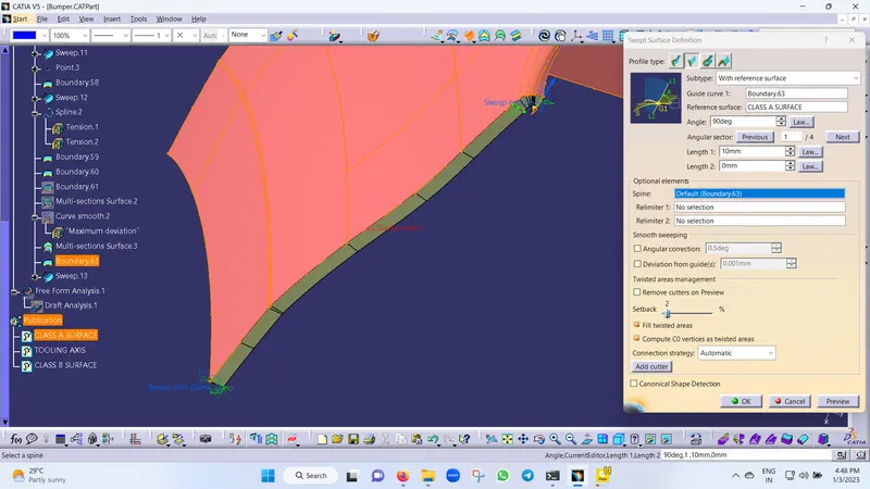
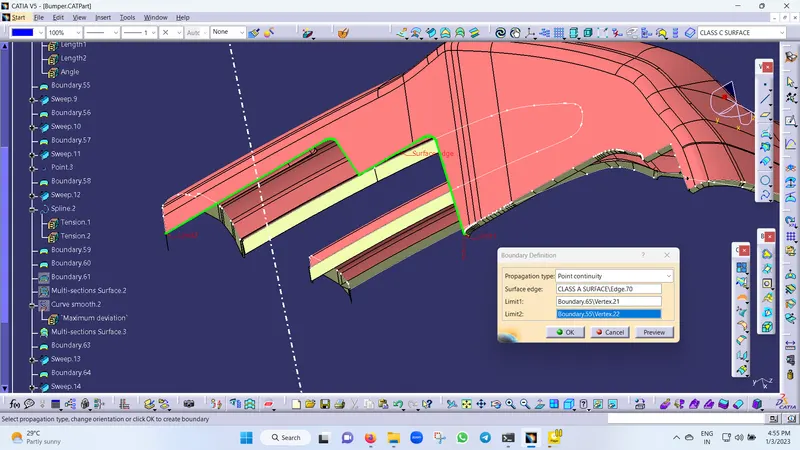
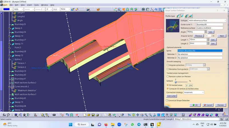
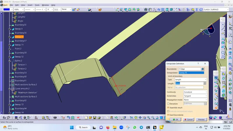
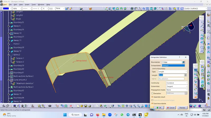
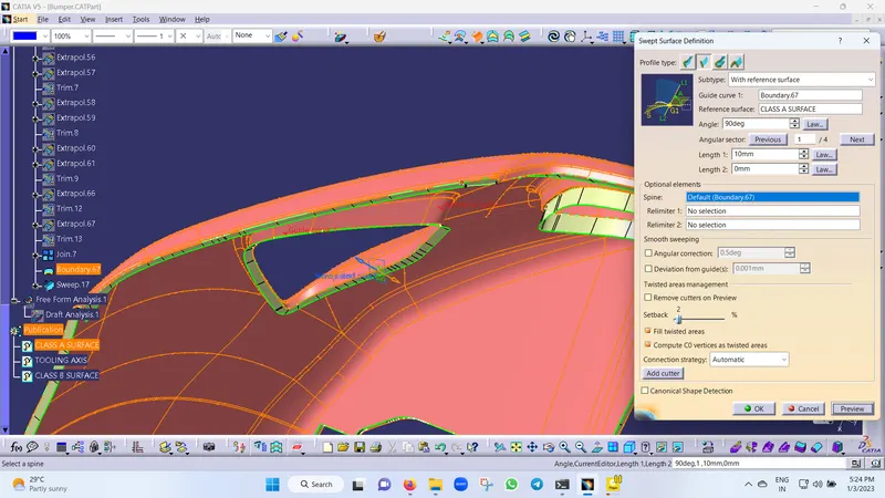
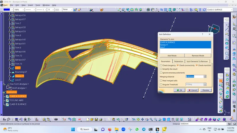
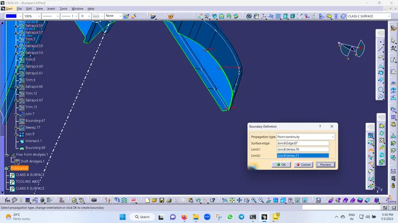
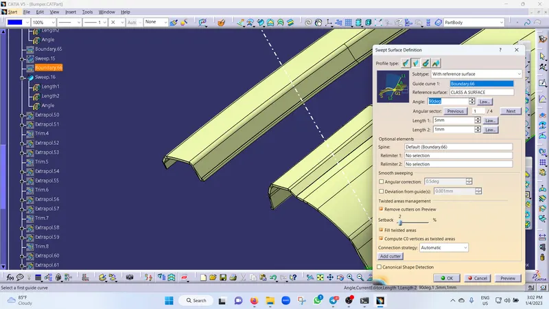

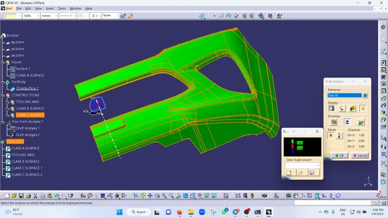
Detailed Report:
Tooling axis creation
- The direction in which the mould opens and closes is called the tooling axis direction.
- Check the connectivity of the surface and ensure there will be no gap between the surfaces and then define the tooling axis.
- While creating a tooling axis please ensure to give the tooling axis on a flat-length surface.
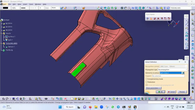
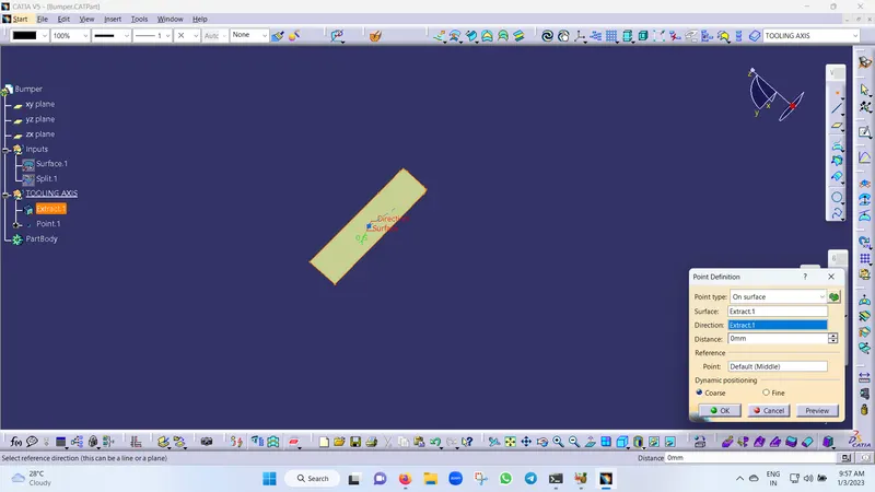
- Create a point on the middle of the base surface by using a point on the surface command then create an intersection for the surface and extract the reference lines which will be helpful for creating the dummy tooling axis using the intersect method by creating a bisecting line.
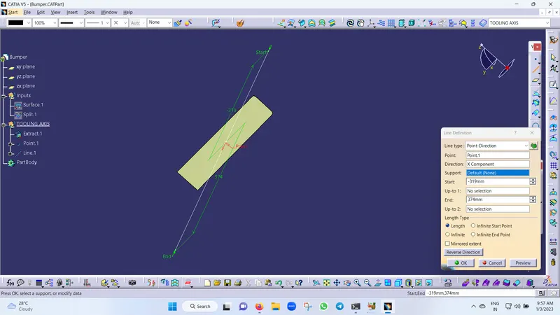
- Use the line command and draw the lines aligned with the extracted lines and extend it to the required length.
Draft Analysis:
First, we analyze the model and then choose a dummy axis in the x and y direction.
As we intersected to proceed we observed that the side walls are not given any draft. Hence we assume the axis normal to the base surface and parallel to the side walls. This surely will create problems because a minimum draft has to be provided.
As the class-A surface is made by another designer only he is authorized to make changes, so we look over this to complete the coin holder for practice.
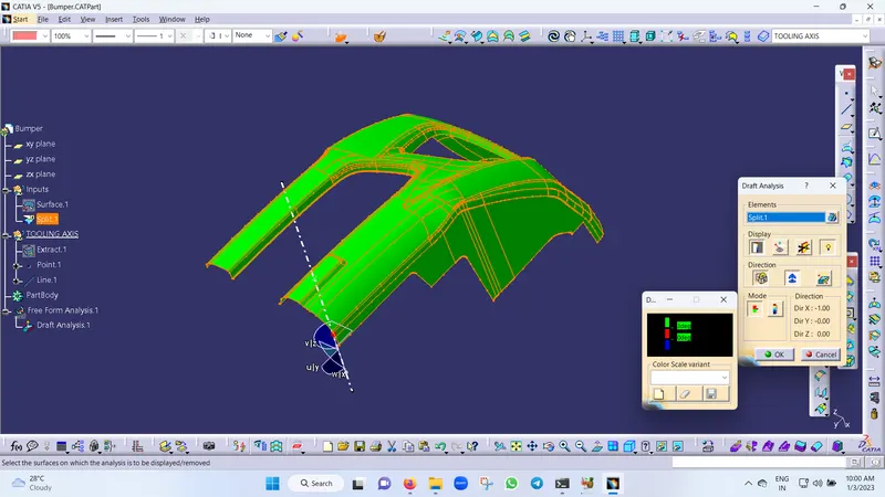
Now we go to insert< analysis< draft analysis and follow the usual procedure to do the analysis.
Align the compass and click on the surface and as expected the model is mostly in red color i.e. negative draft with respect to the axis.
To correct it as best as we can we moved the compass a bit till we got most of the surfaces in green and lock that position.
After hitting ok, we change the direction of the line from the z-axis to the compass direction. The axis will align itself accordingly.
NOTE: as the side wall does not have the draft, this result was expected and a few areas need correction. But still, we are moving forward to
complete the model
Bisecting method:
- Identify on which plane we have to do more operations and create the plane or axis on the component area and define it on the dummy tooling axis direction.
- Intersect the class A surface with that plane then we will get an intersection sketch. Look for the profile (inclined line) which will create a problem and extract it then extend it by using the line command.
- Then create a bisecting line with reference to the lines we have extended and this will be our main tooling axis.
- In this case, we have created a tooling axis along with the Y direction with reference to the base surface.
Class A Draft Analysis:
Final Part Draft Analysis:
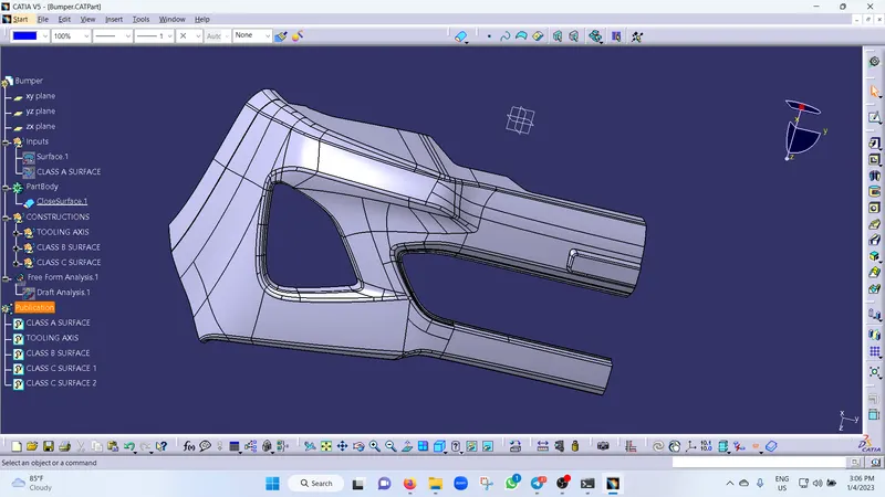
Final part: