Wiring harness design in CATIA V5 - 3D modeling Week 7 Challenge
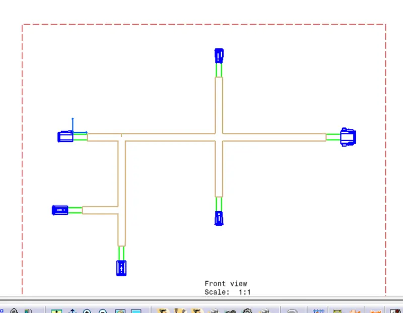
For Representing 3d data into 2d drawing, first it is necessary to to the flatten of the 3d wiring harness bundle geometry.
For creating the Flatten of 3D data it there are some settings to be done as shown in the below images(1).
First we will be create a product file, file>new>product>give the name as context file of the product and save it , now for every flattening assambly first we need to defined FLATTENING PARAMETERS as shown below(1).
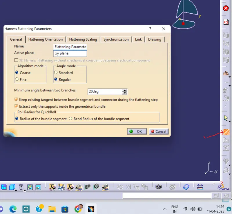
Switch to the ELECTRICAL HARNESS FLATTENING>HARNESS FLATTENING PARAMETERS>a popup will open select the proper setting as shown in image(1)
Go to General tab and do the setting as shown
1
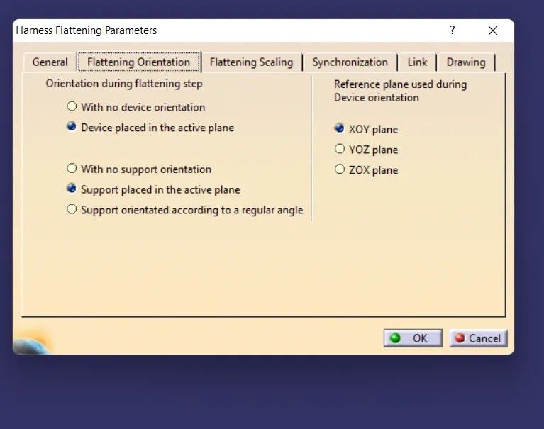
Select the flattening oreintation tab and select as shown in below
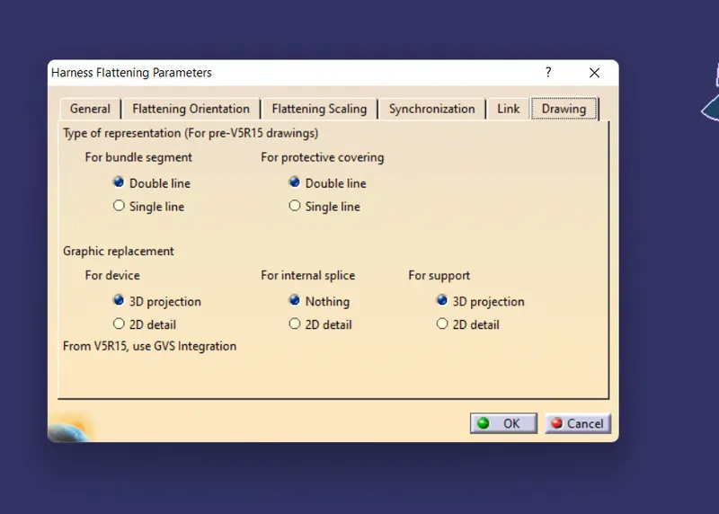
Select the Drawing tab and use the settings as shown in below
A Flatten Parameter will be added in model tree as shown in below image(2)
Now open the 3d wiring harness routing in another window, now always open the two windows vertically so that it will be easy for selection as shown in below image(2).
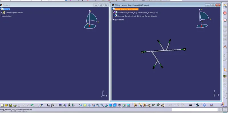
2
Now click on EXTRACT>select the 3D geometrical bundle then the harness routing will be open in the Flattening workbench>now you will notice that name will be added with _Ehf(Electrical Harness Flattening)it indicates that your assambly has been imported succefully. Now save the Assambly see below image.
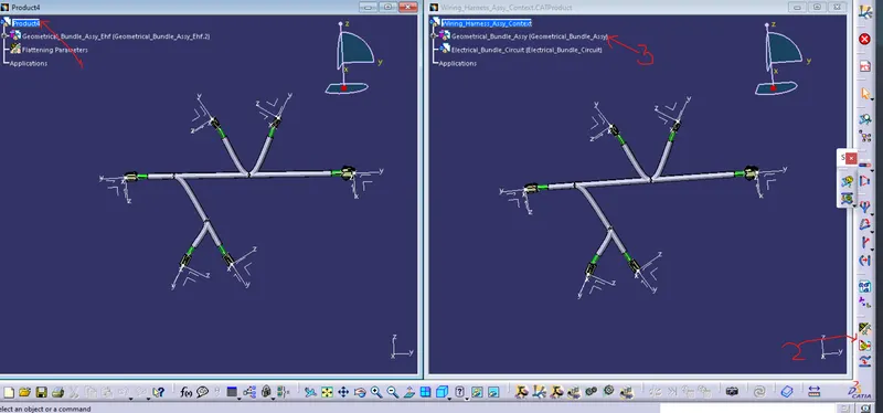
Now Click on FLATTEN>SLECT PLANE (select the face of connector)> BUNDLE>SELECT ALL>OK see below image
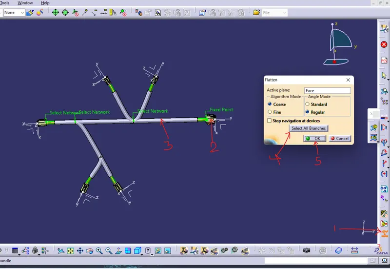
after clicking on ok your routing will be Flattende as shown in below image
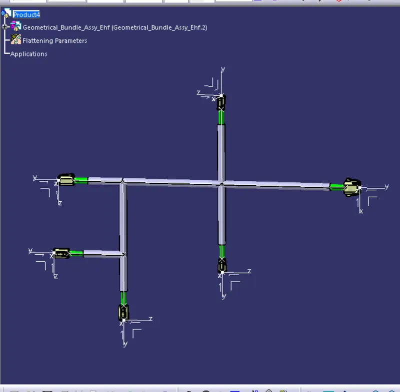
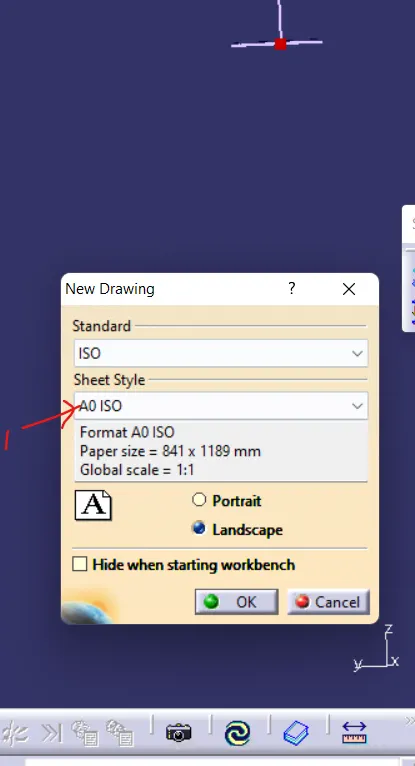
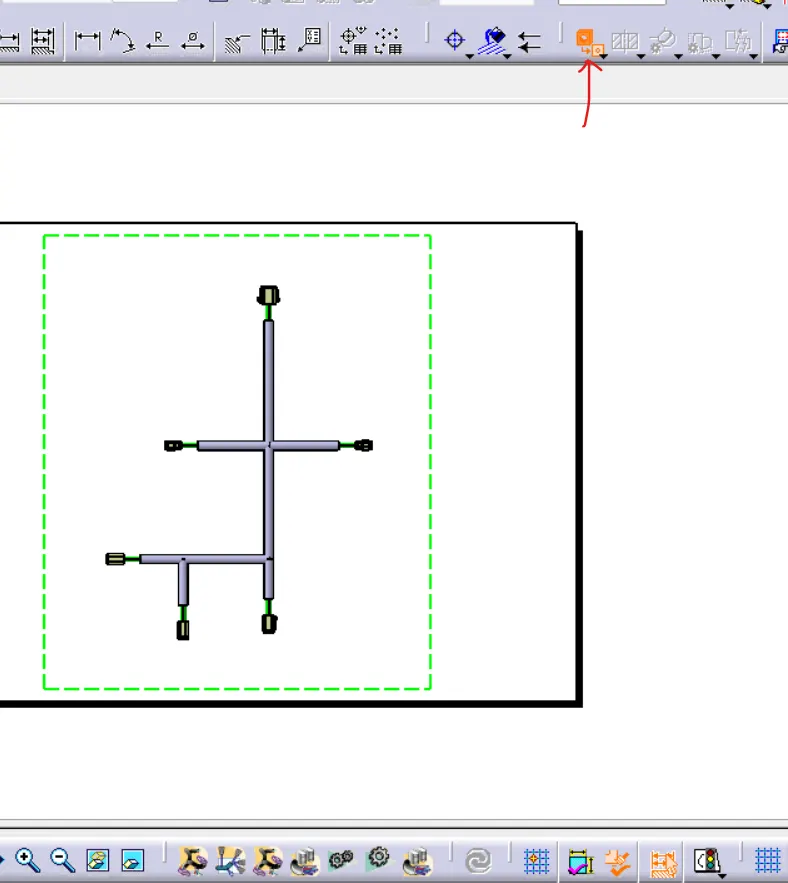
After Flattening we will go for the Drawing, file>new>drawing>selest sheet size A0 ISO(ibelow image 1)>ok here drawing sheet will be open click on front view (below image 2)> go to the flattened and select the front face of the connector
1 2
Rotate to the desired location >click on screen
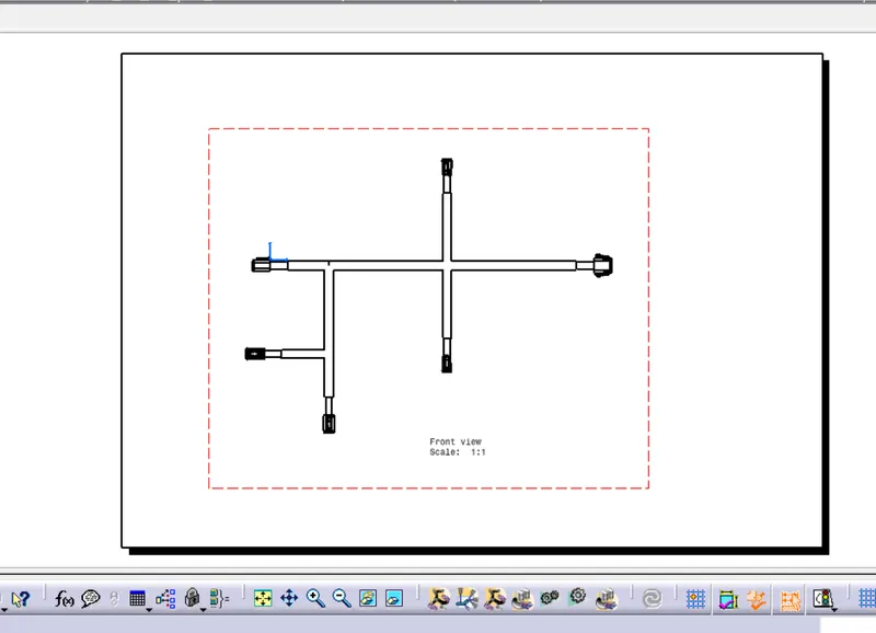
Now we will do the different colour coding for the Bundle, Protective Covering and Connector as shown in below image