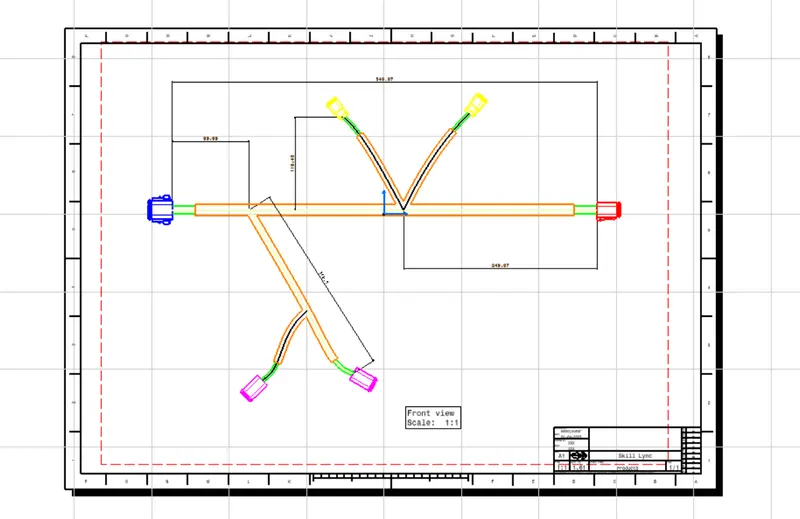
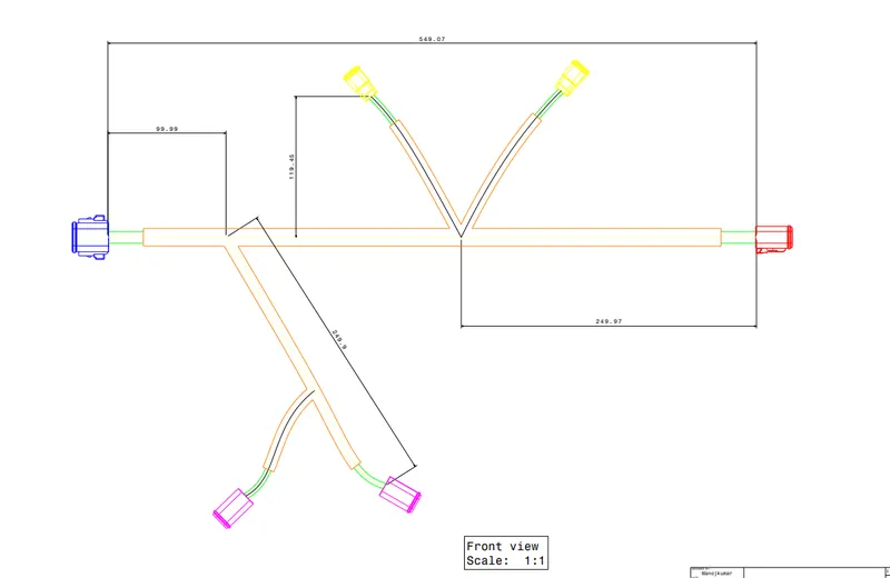
Wiring harness design in CATIA V5 - 3D modeling Week 7 Challenge
Aim:
- Flatten the harness assembly completed in “ week 4 challenge”. Place the flattened view on drawing sheet. Ensure bundles with protective coverings has different visuals on drawing view.
1.DT06-2S
Step-1:
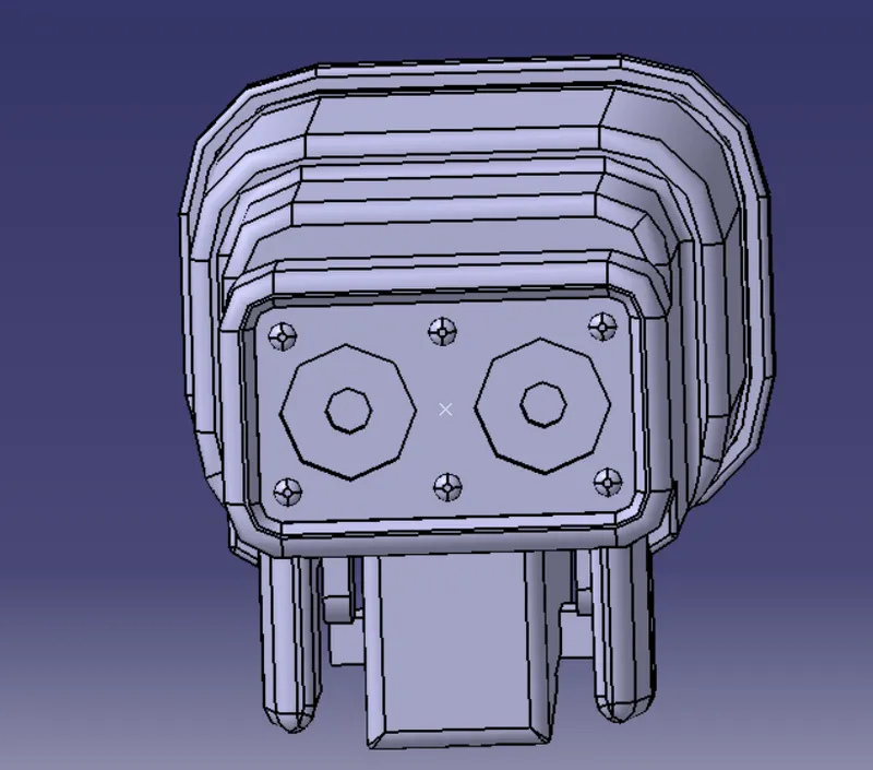
- Create the required Geomterical parts for the connectors
- Define the Bundle side and connector side and create the midpoint and axis for the required sides.
Connector side:
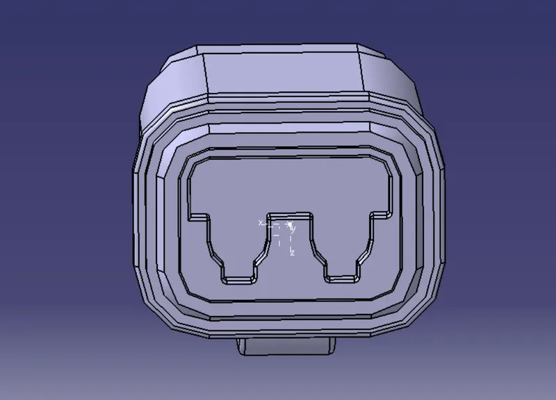
Bundle side:
Step-2:
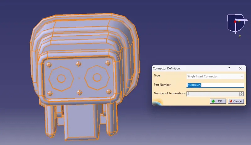
- Navigate to Electrical part workbench
- Define the part as connector
Step-3:
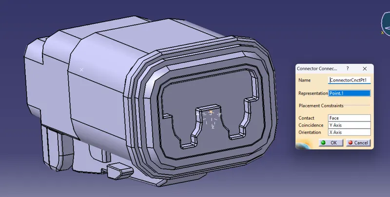
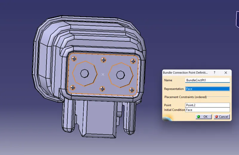
- Define the connector connection point and bundle connection point
connector connection point:
bundle connection point:
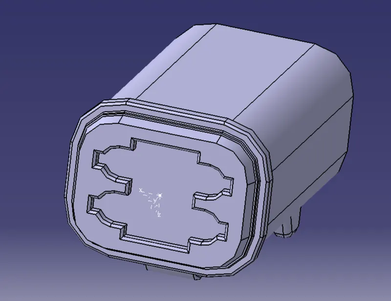
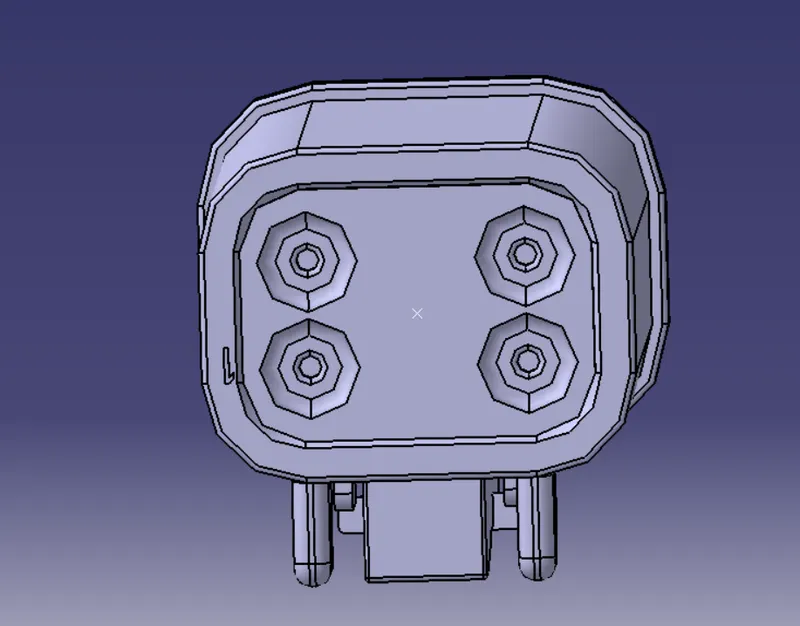
2.DT06-4S:
Step-1:
- Create the required Geomterical parts for the connectors
- Define the Bundle side and connector side and create the midpoint and axis for the required sides.
Connector side:
Bundle side:
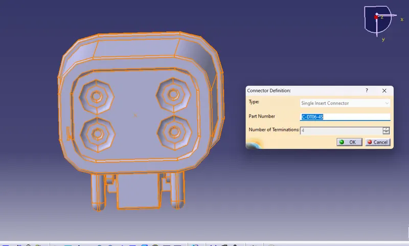
Step-2:
- Navigate to Electrical part workbench
- Define the part as connector
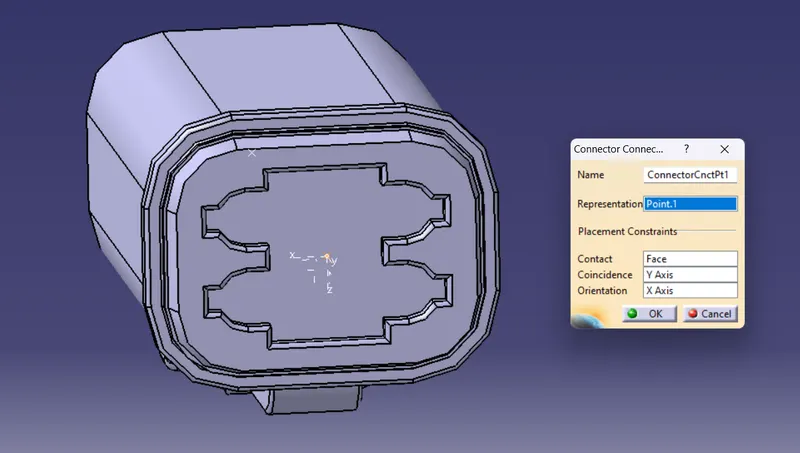
Step-3:
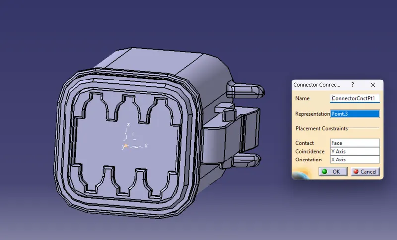
- Define the connector connection point and bundle connection point
connector connection point:
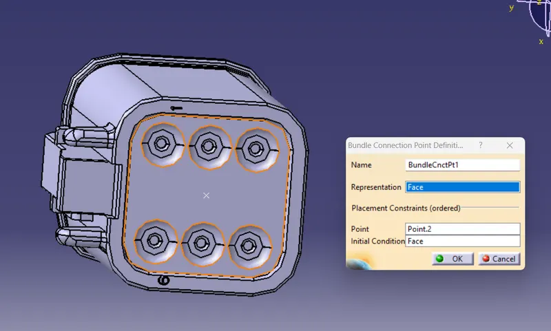
bundle connection point:
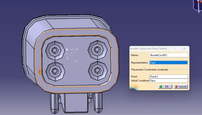
3.C-DT06-6S
Step-1:
- Create the required Geomterical parts for the connectors
- Define the Bundle side and connector side and create the midpoint and axis for the required sides.
Connector side:
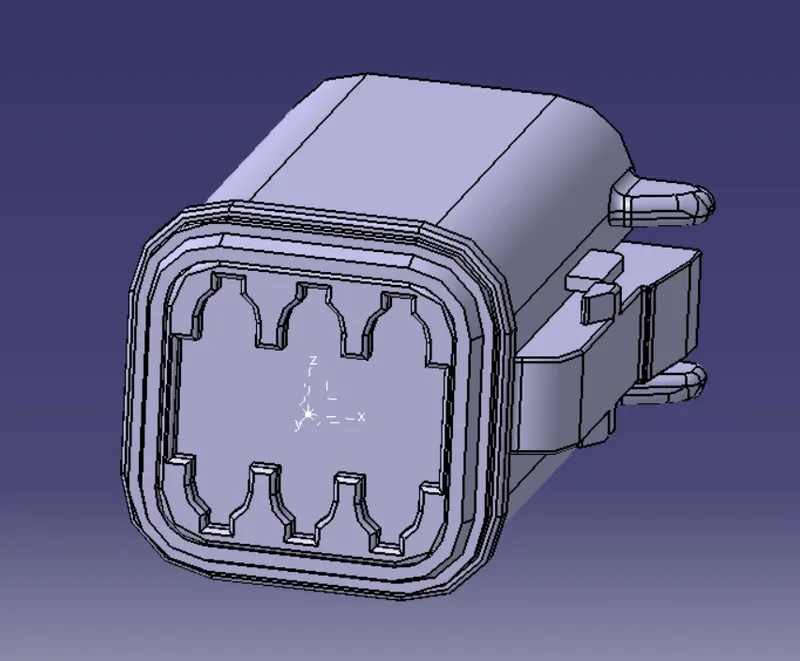
Bundle side:
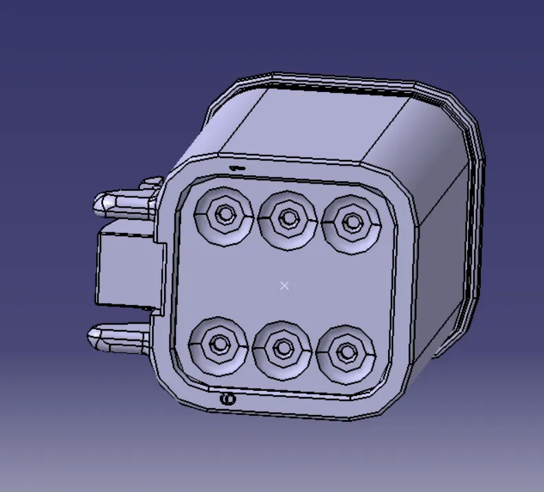
Step-2:
- Navigate to Electrical part workbench
- Define the part as connector
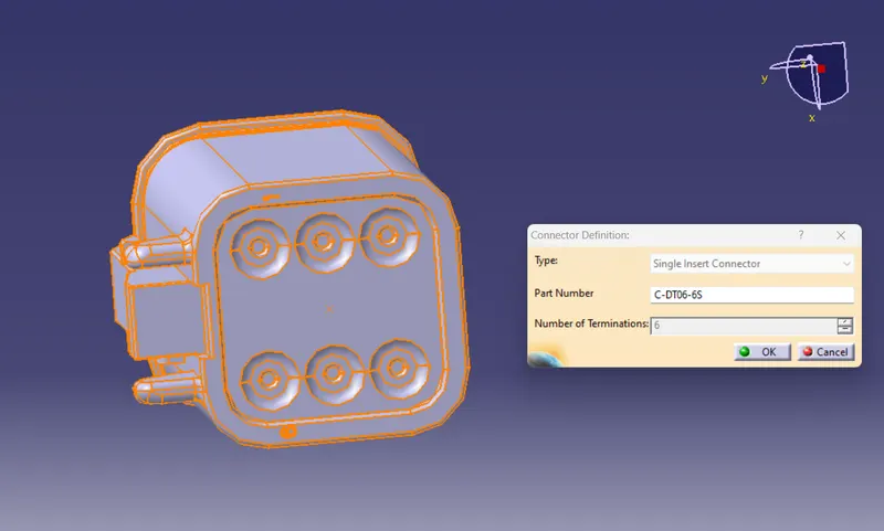
Step-3:
- Define the connector connection point and bundle connection point
connector connection point:
bundle connection point:
4.DT06-08SA:
Step-1:
- Create the required Geomterical parts for the connectors
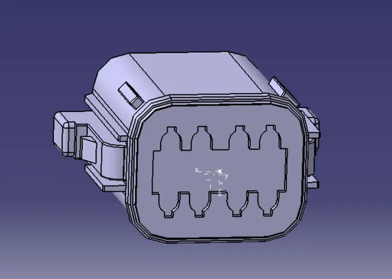
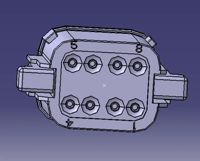
- Define the Bundle side and connector side and create the midpoint and axis for the required sides.
Connector side:
Bundle side:
Step-2:
- Navigate to Electrical part workbench
- Define the part as connector
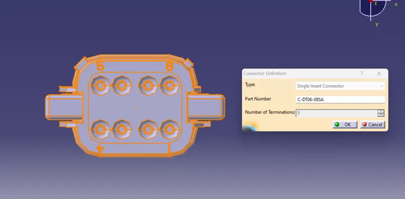
Step-3:
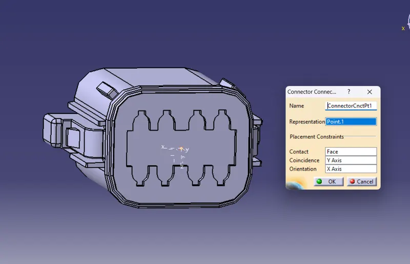
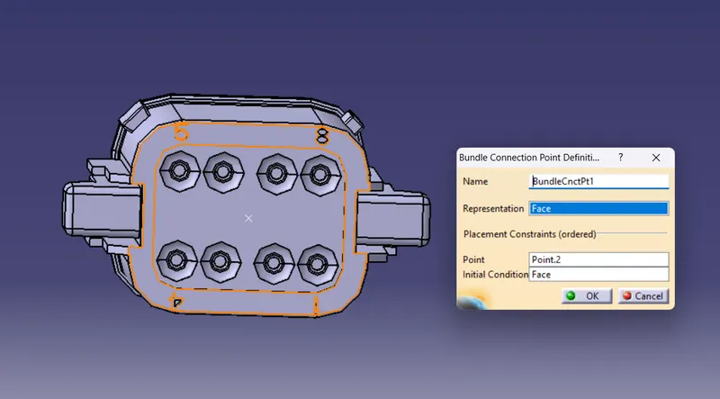
- Define the connector connection point and bundle connection point
connector connection point:
bundle connection point:
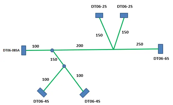
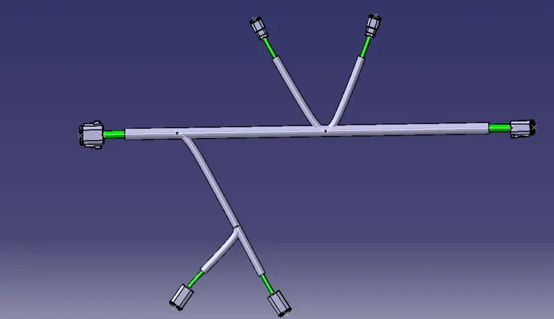
Position the connectors as per the given Diagram and Click on Branch defination and then click on route definition and select connectors in between we want to create branch:
Flatten the harness assembly:
STEP1- Defining Harness Flattening parameters:
- open a new product file in Electrical Harness Flattening workbench
- we should define the harness flattening parameters by clicking on its icon
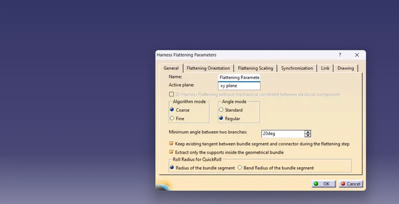
STEP 3- Bring the harness assembly into the newly created Flattening Product by using the "Extract" feature.
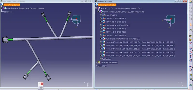
STEP4- Flattening of the harness
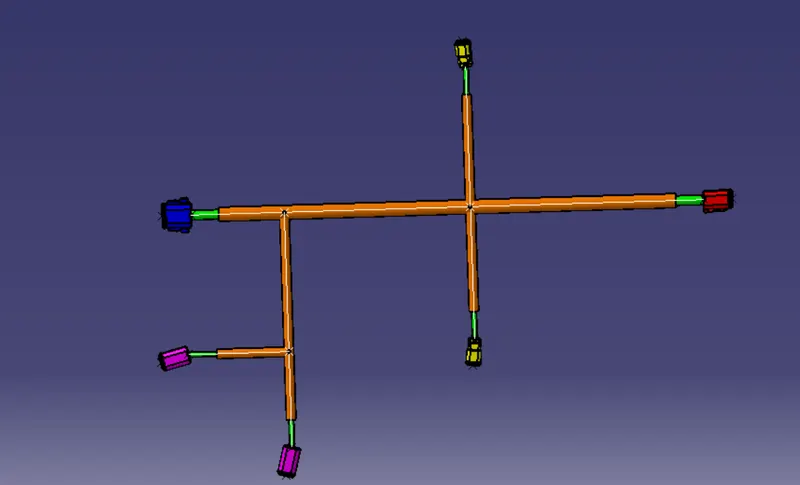
STEP5- Rotate the bundle segments:
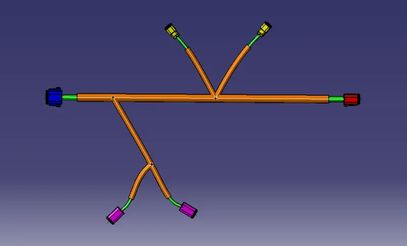
STEP8- Creation of drawing file.