Wiring harness design in CATIA V5 - 3D modeling Week 7 Challenge
AIM
Flatten the harness assembly and Place the flattened view on drawing sheet. Ensure bundles with protective coverings has different visuals on drawing view
HARNESS ASSEMBLY FLATTENING
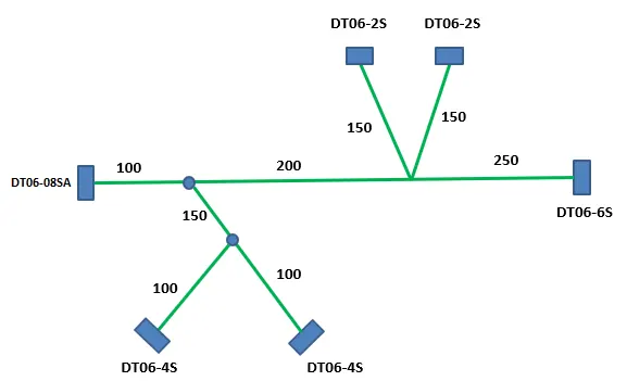
- Defined the all the components electrically and Routed the given harness layout in Electrical workbench .
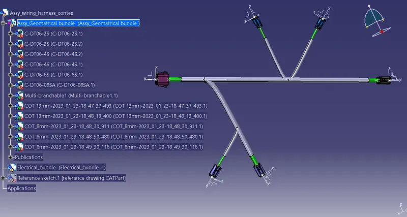
fig.1. Routed Harness assembly
- Then created a new product file "Flattening product "for flattening the assembly.
- switch to Electrical Harness Flattening workbench then select the Harness Flattening Parameter tool and set the required flattening parameters and save it in the same location where the routed harness assembly is stored.
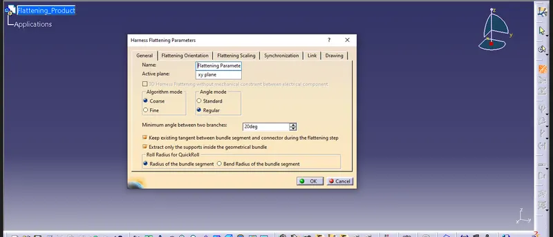
fig.2. Harness flattening parameters
- use "Extract" option to get the above routed harness assembly in the Electrical Harness Flattening workbench .Then the Harness assembly product file will be vanished in addition "Ehf " extention added to the imported product assembly file.
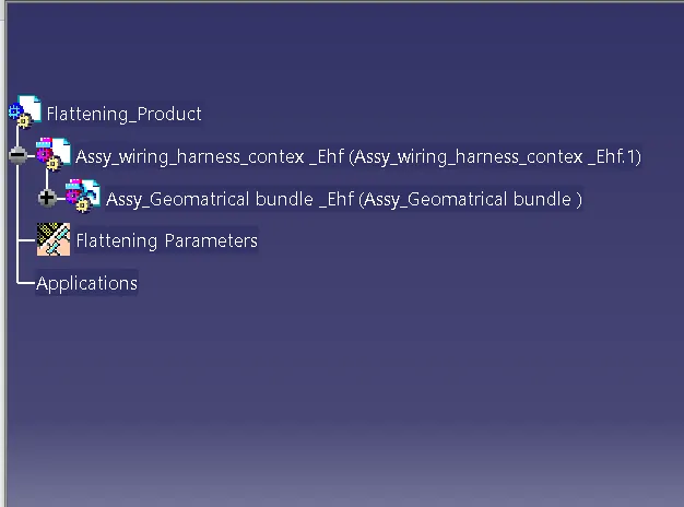
fig.3. harness assembly added to the flatten assembly
- For flatten the geometrical bundle select the "Flatten" option and select the required plane and branches for flattening. 'select all branches' optioin to select all the bundle segments in a single click it is only applicable when there is no discontinuity in the bundle segment. Then select OK to flatten the harness assembly.
- use manipulator "Rotate,Quick Roll, Arrange Junction etc " to arrange the branches in proper position .
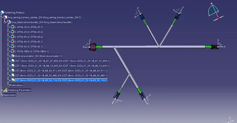
fig.4. flattened view of harness assembly
Next working in the draft workbench to Place the flattened view on drawing sheet .
- Flattened view on drawing sheet depends on the Harness Flattening Parameter settings .Inside harness flattening parameters use drawing menu ,there is types of representation for bundle segment and protective coverings in the drafting sheet . single line and double line representations available for both components .
- create the new drawing sheet and select front view option to project the view in to the sheet.selecting flat faces of the connector (flatten plane )and orient the view as per the requirement.
- Go to the properties of the view and select the '3D Wireframe' on and use ' Is always visible' option to clear view of Wire bundle, connectors and protection coverings.
- Insert the title block template and fill up the required details.
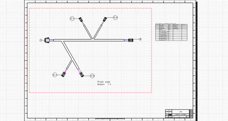
fig.5. flattened view on drawing sheet [both bundle segment and protection coverings represented as double line ]
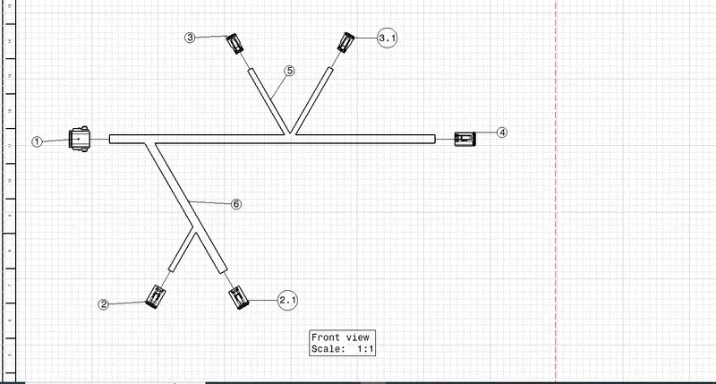
fig.6.bundle segment represented as single line and protective coverings represented as double line