Hood design-Week 2
CAR HOOD DESIGN
AIM:Design Hood Outer Panel, Inner Panel and the necessary reinforcements by following the Master Section mentioned with the Design parameters.
1. INTRODUCTION
- A car hood, also referred to as a bonnet in some other countries, is the hinged cover that rests over the engine of a front-engine vehicle.
- Its main function is to direct access to the engine, bettry and other crucial parts of the cars for repair and maintenance and to protect these parts from direct sunlight and dust.
- A concealed latch is typically used to hold down the hood. Hoods sometimes also contain a hood scoop, wiper jets, power bulge, and/or hood ornament.
- Car hoods are typically constructed from steel and sometimes from aluminum. Aftermarket car hoods may be constructed from various other materials, including carbon fiber, fiberglass, or dry carbon .
Car bonnet is the important component which is utilized for several purposes at the front. Therefore, bonnet must be designed in suitable manner and it should minimize the hindrances from the disturbance caused by the external environment on the hood and its components below it. When the car is in running condition, the resisting forces from the air acting on the hood therefore the design of the bonnet should be made aerodynamic to reduce the air resistance.

fig 1 Hood open view
2.HOOD STRUCTURE
The bonnets of the most vehicles are basically fabricated using the sheet metal structure, a good energy absorbing structure so it causes substantially a small threat. Outer and inner stiffener panels are made or fabricated by using the of sheet metal structures therefore environment used is surface modelling. Since the hood assembly is a sheet metal component, hood structure is vulnerable to the vibrations. The source of the vibrations could be the engine generated vibrations, the vibrations due to the un-evenness in the road surface, and aerodynamic interactions of the hood surface when the vehicle is in motion. Excessive vibrations will put an impact on the passenger's ride comfort, and also make the structure susceptible to fatigue failure. Too many vibrations also affect the functioning of the locking mechanism of the bonnet, considerably risking the unlocking function and bonnet will be open up while the vehicle is in motion. Because of the many ongoing efforts are to reduce the weight of the vehicle, the thickness of the bonnet is being reduced to its possible values. This could considerably increase the severity of the vibrations that the structure is subjected to. Hence, determining the fundamental frequencies of the bonnet structure and its behaviour at those frequencies is necessary.
3.HOOD DESIGN CONSIDERATION
- Head Clearance
- Pedestrian safety
- Hood opening angle and Location of stay rod
- Latch Operation
Full opening angle is mainly depending on the headclearance criteria, geometry of hood assembly and hingeassembly. As per benchmarking study the angle is 60 to 65degree
3.1 HEAD CLEARENCE
While designing the hood head clearance also consider because when the hood is in open condition it shouldn't collide or hit to head of the worker. If the open angle is less, high chance to hit the striker. It depends on the average height people in that country.
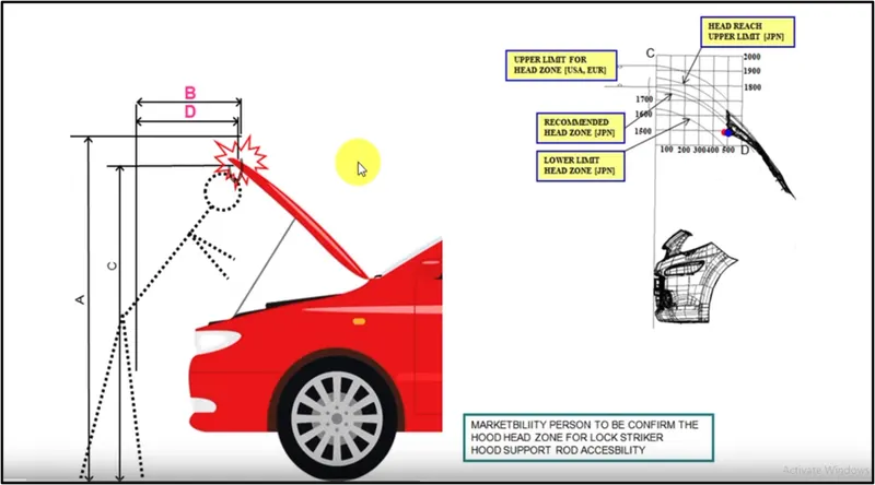
fig 3.1 Hood Head Zone Selection Criteria
3.2 PEDESTRIAN SAFETY
Besides functioning as an engine compartment cover, the bonnet of modern vehicles can also help manage the impact energy of a pedestrian’s head in a vehicle-pedestrian impact. However, a bonnet’s ability to absorb impact energy may be impeded by the proximity of the bonnet to components packaged inside the engine compartment, i.e., by its underbonnet clearance. For example, for a given bonnet design, the bonnet’s ability to absorb impact energy through deformation can be significantly reduced when the bonnet and engine block are in close proximity.
To reduce the death of pedestrian and injuries in the traffic, measures from the automotive industry as well as environmental changes are required.The European Enhanced Vehicle Safety Committee has developed test procedures to estimate the level of pedestrian protection for the front parts of the vehicles. Based on the report, legal requirements have been derived. The European directive consists of head impact, upper leg impact and lower leg impact .To test how good the cars is at pedestrian protection, the car industries performs different tests on the cars that simulate an real life accident with head impact, upper leg impact and lower leg impact. In the hoods perspective, the head impact protection is the most common and is in the highest priority.
The headform test area is defined based on the pedestrian wrap-around distance (WAD) , in which child and adult headform test zones are separated. The test zones cover almost the full width of the vehicle, so that the overall pedestrian protection can be evaluated throughout the vehicle front-end structures. Once the tests are conducted, the impact responses are then assessed by points and rated in colour. The impact responses measured in the pedestrian impact tests and their associated injury criteria.
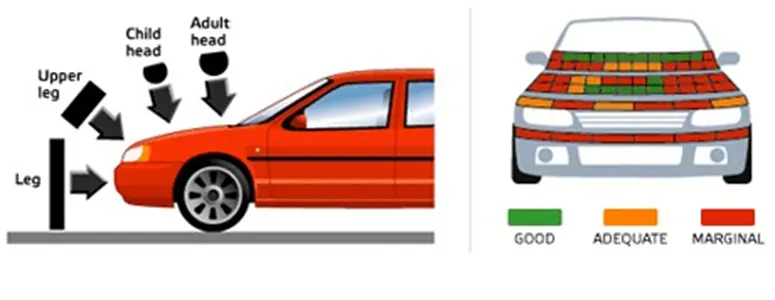
fig 3.2.a Euro NCAP pedestrian protection test and rating
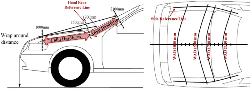
fig 3.2.b Headform test zones based on wrap around distance (Euro NCAP)
3.3 HOOD STAY ROD
The hood stay apparatus can safely keep an engine hood in an open state even if an external force is abruptly generated due to vibration, wind, and the like. The hood stay apparatus can also facilitate an opening/closing operation of the engine hood.
TYPES OF HOOD STAY
3.3.1.SUPPORT ROAD
Stable rods intended to safely hold up vehicle hoods during inspection and repairs.The hood is provided with a hoodstay rod having a predetermined length to keep the hood open. Hood Open condition one end of the rod hold on the body side ,other end on the predetermined position of inner panel. To fix the rod holding point provide on the hood inner panel.The support rods provide in right hand side of the vehicle to prevent the interference while installing battery. Allowed bending for the stay rod is less than 35mm.
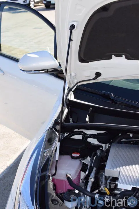
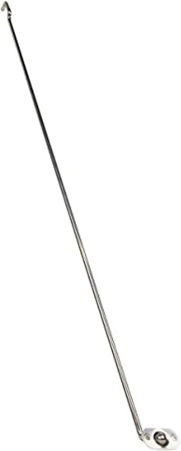
fig 3.3.1 support rod
3.3.2 GAS STAY
A gas strut (also referred to as a gas spring) is a spring that operates due to the force exerted by the compressed gas (usually Nitrogen) stored inside the cylinder. Luxury carmakers provide a gas strut to lift the hood and hold it in place. It takes minimal efforts to lift .
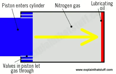
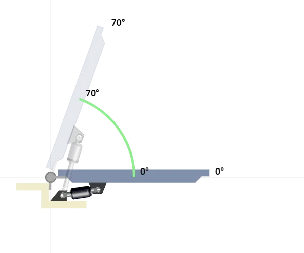
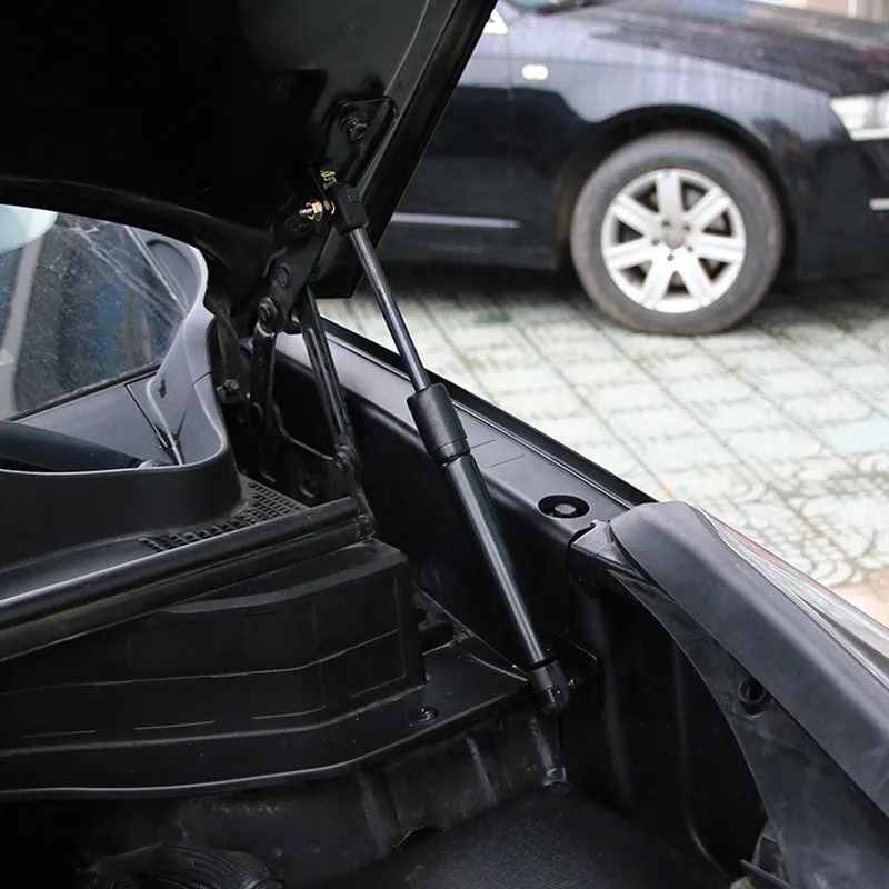
fig 3.3.2 a Gas stay working fig 3.3.2 b Gas stay
3.4 HOOD LATCH AND STRIKER
The hood latch system is a vital component in every automotive. It is located behind the grille, directly under the hood striker, which is on the hood. The hood latch
has many important functions. it is necessary to keep the engine covered and protected. The hood latch system ensures that the hood stays locked, therefore protecting the engine and the many other parts that reside within the hood of the car.
The hood latch system must be able to catch the striker of the hood upon closing and instantaneously, as well as automatically, lock. Once in the locked state, it must
remain locked and only unlock upon the operator’s control.
Striker bolts to the underside of the hood at the front. It engages the hood latch when closed.it must be tangentially perpendicular to the circle made from hinge axis futhermore inaccurate position may result in improper closing of hood.
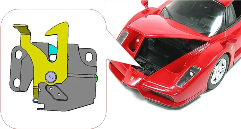
fig 3.4.a hood striker fig 3.4.b hood latch
3.5 MANUFACTURING PROCESS
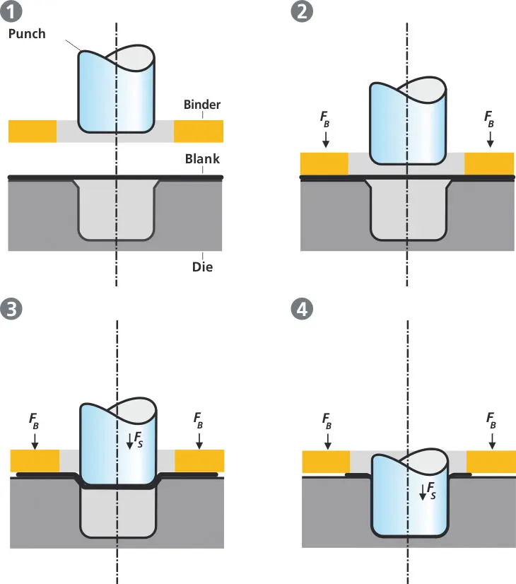
The rigid tools consist of a punch, die and binder. In deep drawing, the plate holder closes after the metal sheet blank has been inserted.Next the sheet is clamped between the die and the binder. This process slows down the flow of the sheet while it is being drawn and thereby prevents wrinkles from forming under the binder. The punch stretches the sheet over the die radius and forms it in the die. The amount of punch force necessary for forming is thereby continually increased up to the lower dead center of the punch.
Whereas in pure deep drawing there is no reduction of sheet metal thickness, forming is achieved in stretch forming purely as a result of a decrease in sheet metal thickness. Stretch forming is extensively used for the forming of only slightly curved parts with low depth of draw (e.g. roofs, doors).
When drawing complex car body parts in practice, there is usually a combination of stretch and deep drawing involved. It is necessary that the sheet metal is stretched as well as possible without reaching the material’s limits (e.g. splits, wrinkles).
There are approximately 300 to 400 sheet metal parts which fit together to form the body of a car. In order to manufacture high quality sheet metal parts optimally for their particular use, specialized software simulates the complete deep drawing process.
3.5.2 HEMMING
One of the major joining technologies of outer skin components is hemming. The hemming operations produce a metal-form joint between the outer skin part and the inner part of the vehicle body. The process is in general combined with a bonding process and the sheets are joined without any additional fasteners. This technique combines several advantages, such as low weight of the joint, increased component rigidity and minimized risk of injury, due to the elimination of sharp-edged end pieces. The two processes of conventional press hemming and roller hemming are generally used to manufacture vehicle body parts, such as engine hoods, doors, trunk lids andfenders. In contrast to the conventional press hemming the roller hemming is completed incrementally by an industrial robot driven hemming roller. The advantages of roller hemming against the conventional process are based on technological and economic criteria. Roller hemming allows a more adaptive process, which offers advantages when producing lower numbers of units.
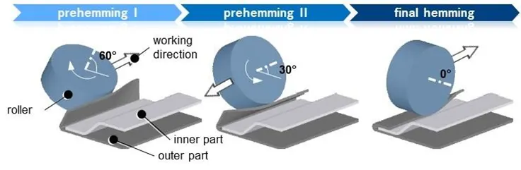
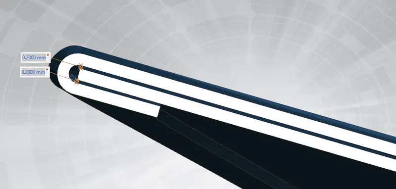
fig 3.5.2 a Roller hemming proces
The first two steps are called prehemming and the third one is called final hemming. In the roller hemming process, three different rollers usually are exploited, i.e. using three rollers in three different steps of hemming process. In the prehemming steps the roller folds the outer panel to get 60 degree and 30 degree respectively. But in the final hemming step, roller would completely fold the outer panel on the inner panel. This would happen by applying extra forces.
Inaddition adhesive bond provide for excellent joining of panels it also reduce vibration .here this design 0.2mm clearence provided for hem glue .
proper relief provided at the corners to maintain good hemming joints .
4. HOOD COMPONENTS AND ASSEMBLY
Hood assembly includes inner panel, outer panel, hinges, latch and reinforcements. The upper and stiffener panels are joined through the process of hemming or both panels are joined by using the adhesive namely mastic. Spot weld can be made where it will be necessary. Sandwich construction of the hood structure that will increases the capability of the hood’s ability to absorb the energy impacted by the external forces which are acting on the bonnet.
Data used for hood design
Hood Thickness Information
- Outer Panel Thickness = 0.75mm
- Inner Panel Thickness = 0.75mm
- Reinforcement Thickness = 1.5mm
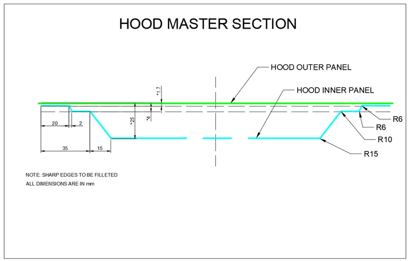
fig . Master section for hood design
4.1 HOOD OUTER PANEL
The outer panel skin surface from style department with proper aesthetic look, gap and falseness. Outer hood panel follow the aerodynamiccriteria.The inner panel of the hood is not visible to the customer but this is the engineering feature of the outer panel. The outer panel has the aesthetic look to it but on its own is very weak and not capable of handling force during impact.Hood outer pannel is made of sheet metal having thickness of 0.75 mm.The outer panel and inner panel joint through the process of hemming.
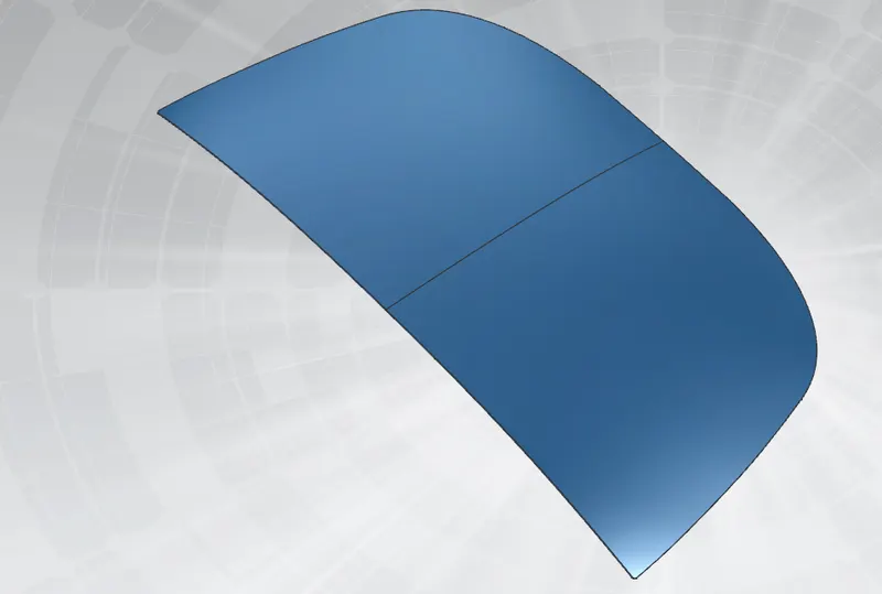
fig 4.1 design of hood outer panel
4.2 HOOD INNER PANEL
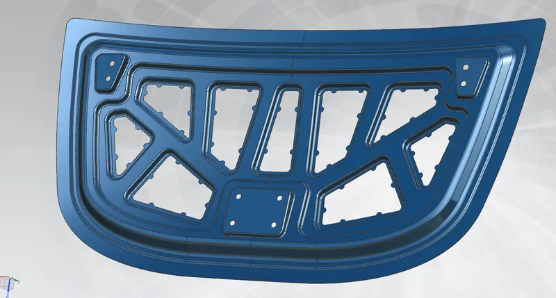
fig 4.2 Hood inner panel design
4.2.1Emboss
Sheet metal embossing is a metal forming operation in which the sheet metal is stretched into a shallow depression. Sheet metal embossing is generally used to create logos, lettering, small depressions, etc. It is also used to create desired non-slip surfaces as well as other geometric features on the sheet metal. In sheet metal embossing, the deformation of the metal takes place because of stretching of the metal (or tensile force acting on the metal), due to which the sheet metal is subjected to excessive thinning and fracturing. Thus the depth to which the material is depressed depends upon the thickness of the sheet as well as stretch ability of the material. The three factors mostly determine the quality of the embossed product
- Pressure: Pressure applied to the sheet metal should be controlled during embossing.
- Heat: Heat level should be maintained consistently during the embossing to get the perfect impressions.
- Die depth: The depth of the die should be adjusted such that the extreme thinning or failure of sheet metal does not occur.
The embosses on the inner panel are designed to distribute the impact forces on the outside which protects the passenger during a crash. These embosses are designed in a particular shape (Y or V shape).
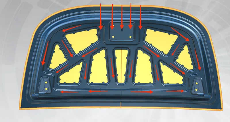
fig 4.2.1 emboss design and force distribution
The inner panel design suchaway that the force distribution towards the hinge area to protect the passengers .
4.2.2 mastic points
mastic adhesive use to bond hood outer panels to the hood inner panel structure. This one‐component synthetic rubber sealer remains elastic after curing to reduce panel flapping and to prevent panel distortion.
- energy efficiency by bonding innovative materials for lightweight design
- Driving comfort by reducing squeaks; rattles; and noise, vibrations and harshness (NVH)
- Safety by improving assembly strength
mastic provided between hood inner panel and hood outer panel to better bonding .it also maintain excellent NVH, avoid spot weld to maintain upper hood surface regularity. The mastic diameter is 80 mm .It is the strengthen diameter of mastic rubber.
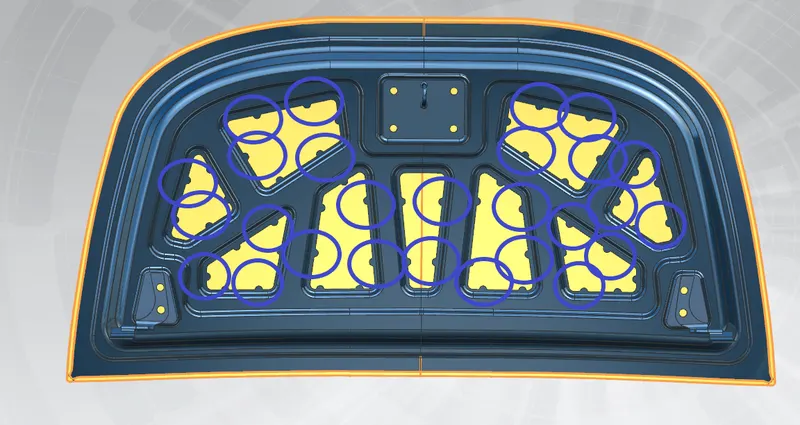
fig 4.2.2 Mastic points provided in hood design
4.3 HINGE
The hinges also guide and hold the hood when open &close. Their kinematics analysis had done to ensure that the hood does not contact other components.The hinge joining area is again a functional area of the hood panel.hinge reinforcements provided there in order to strengthen the component and make the functioning smooth.A pair of hood hinges installed in the front of the vehicle.Both hinges should be in same axis for smooth movement of hood .
Hinge reinforcement provided to reduce imapct of collisions in to the passangers cabin. Generally reinforcement of hinges are made 1.5mm thickness.
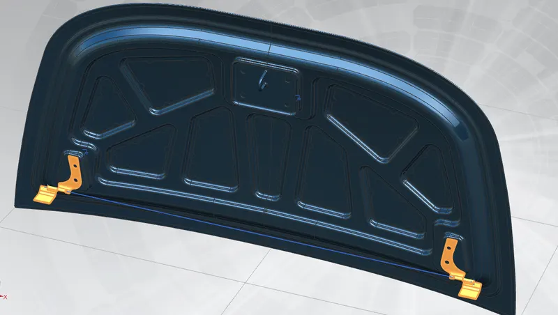
fig 4.3 Hinge assembly
4.4 STRIKER
Striker bolts to the underside of the hood at the front. It engages the hood latch when closed.it must be tangentially perpendicular to the circle made from hinge axis futhermore inaccurate position may result in improper closing of hood.Proper reinforcement provide on the striker area.
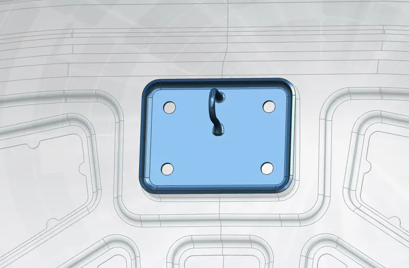
fig 4.4 striker
4.4.1 latch trajectory
striker assembly based on latch trajectory .The hood latch system must be able to catch the striker of the hood upon closing .it must be tangentially perpendicular to the circle made from hinge axis.This path follow the striker on opening and closing of hood .
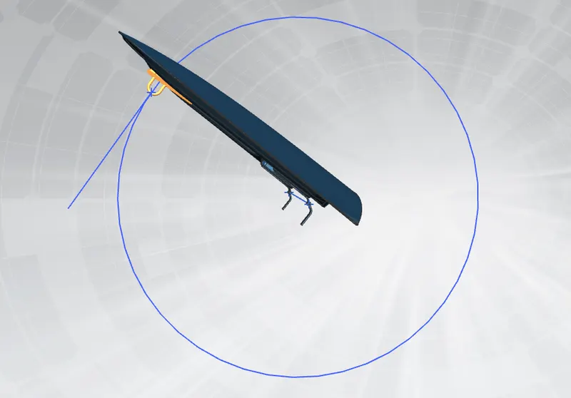
fig 4.4.1 latch trajectory
5. CONCLUSION
- The hood designed based on master sketch by using NX CAD. Both the outer and inner panels designed. Based on given data porper reinforcemets provided for the hinges and striker . The final hood assembled using NX CAD software.