Wiring harness design in CATIA V5 - 3D modeling Week 5 & 6 Challenge
WEEK 5 AND 6 CHALLENGE
The challenge involves harness connections between harnesses A and B. To start the task, CAD files for all the connectors were downloaded and then defined.
Connector Definitions
- CAD files extracted
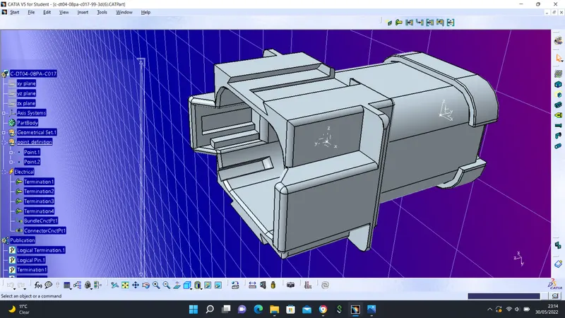
- Points and axis points were defined for both connector connections and bundle connections for all the connectors
- Connector defined
- Bundle Connection Points are defined for all connectors
- Connector Connection Points are defined for all connectors
SAMPLE CONNECTOR DEFINITION
HARNESS A
After all the connectors are defined, the workbench was switched to Electrical Harness Assembly where Geometrical Bundle was activated. All the connectors were routed using the Multi-Branchable Document command.
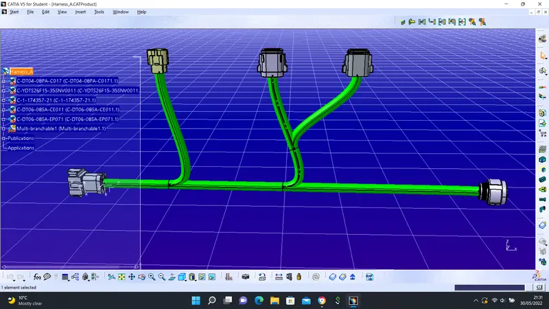
Branch Point was also created for the sub-branch.
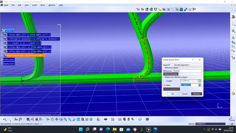
HARNESS B
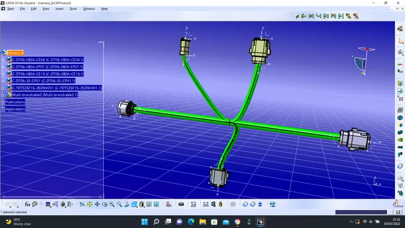
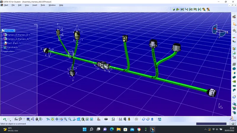
Assembly Harness A and B
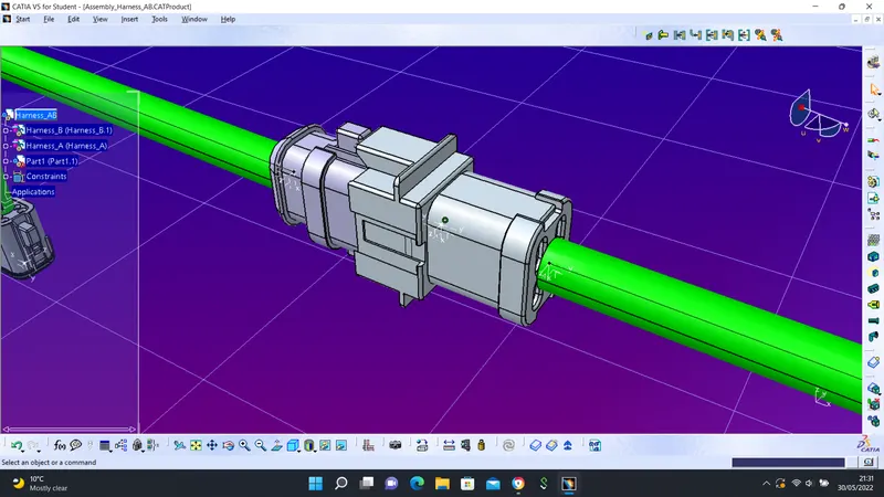
Harness A and B were assembled. The connection was completed using the Connect Electrical Device command using the axis defined.
Connect Electrical Device
Bundle Continuity Check Harness B
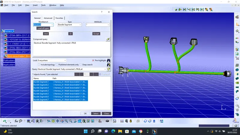
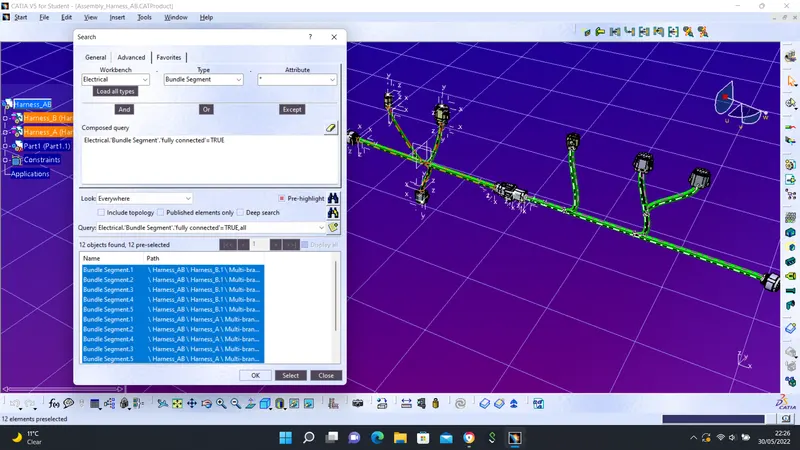
A continuity check was performed on the harnesses. This ensures there will be no electrical bridge in the harness. To perform this task, certain parameters were defined:
- Type: Bundle Segment
- Attribute: Fully Connected
- Condition: TRUE (The TRUE conditions mean all the connected bundles will be listed on the page )
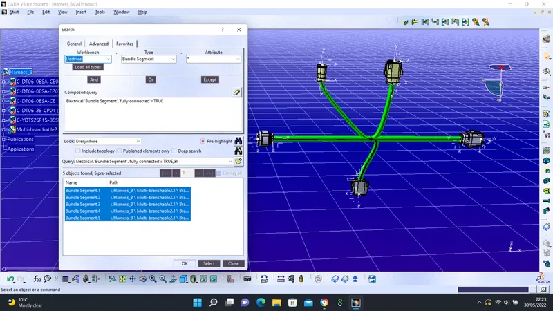
Bundle Continuity Check Harness A
Bundle Continuity Check Assembly Harness A and B
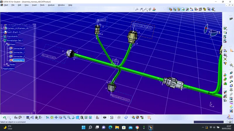
Annotation Connector
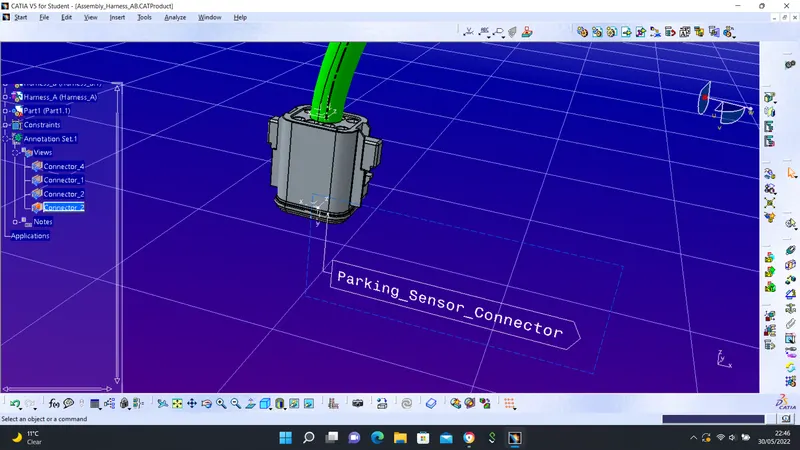
The 3D annotation is used to show connector functions and additional information that might be required for a third party to understand what each connector represents. A sample 3D annotation was performed in the image below.
The task required include:
- Front Plane created using the View from Reference command
- Flag Note with Ladder option was preferred and the connector details were entered.