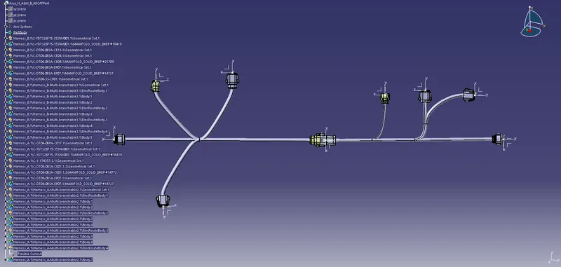
Wiring harness design in CATIA V5 - 3D modeling Week 5 & 6 Challenge
-Create a seperate folders for creating Harness A and B
-Open new product and name it as Harness A
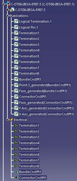
-Import all components and electrically define the elements as connectors in the electrical part design.
Harness_B
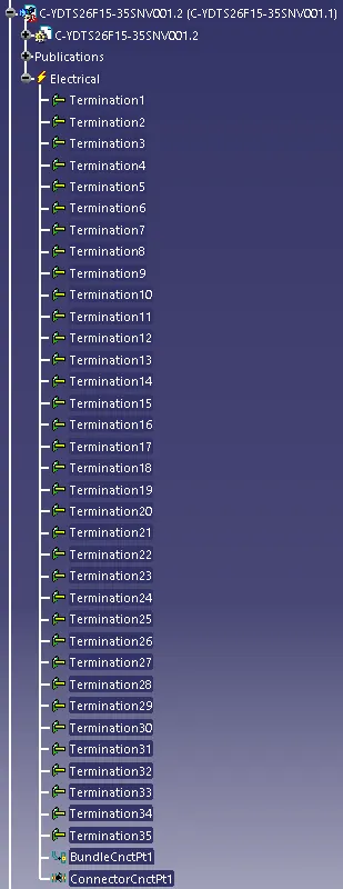
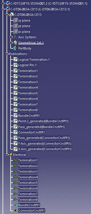
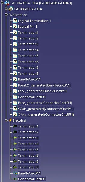
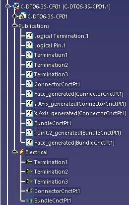
Harness_A
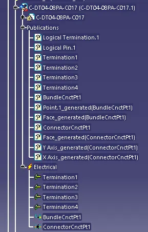
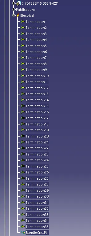
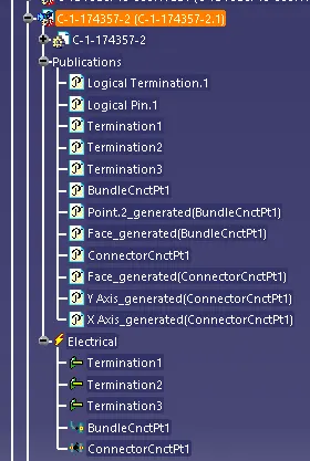
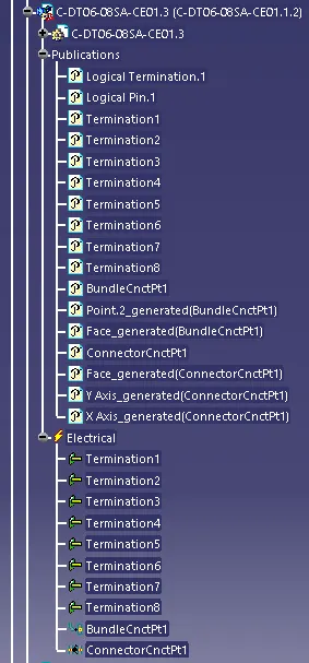
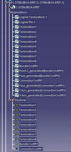
- Open the Harness_A product file in assembly workbench.
-Allign the connectors according the requirement by using by taking one element as reference ,use the compass to move connectors from
-Make use they are in same plane.
-Select the geometric bundle in the Creation toolbar.Now the file is electical defined.
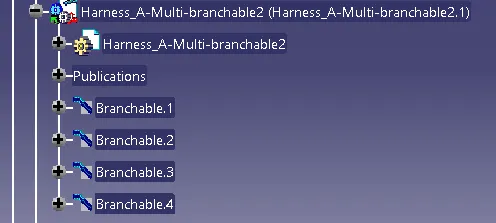
-Select the Multi-branchable document in the Creation toolbar.
-select the connectors to routing the bundle.
-set the diameter as 10mm,Bent radius ratio as 1.4 and slack 0.
-Select the Add Branch point in the Creation toolbar.
-Select distance were to create point in the bundle.
-Create sub-branch as required .
-Similarly create the Sub-bundle as required.
-Similarly Create Harness_A product file and follow the same procedure.
-Open a new product file and rename the file as Harness_A & Harness_B
-Copy and paste Harness_A and Harness_B into the Design tree.
-Allign to a plane.
-Select the Electrical connect devices from the Electrical connection point definition toolbar.
-select the 5 and 6 connectors to connect.
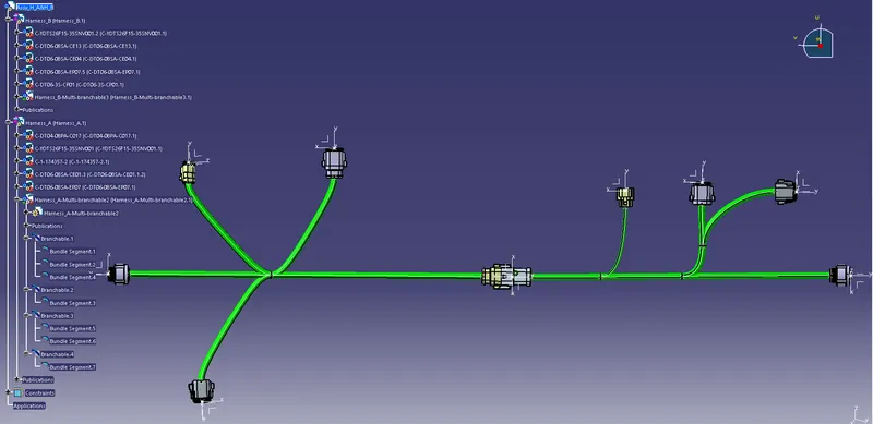
1.Bundle Continuity
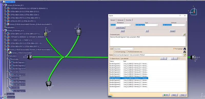
-Click on edit -search-advanced
-Set the Workbench- Electrical,Type-Bundle segment,Attribute-Fully connected.select true.then click on search.
-List shows the continuty of the Bundle.
-
2.Annotation
-Open the Assembly workbench
-Select view from reference from annotation toolbar.
-select the plane to show annotation.
-Select the Flag note from leader to open annotation box.
-Type the note.
-Similarly do for all connectors.
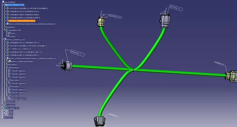
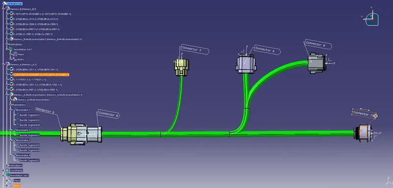
3.Bundle Warning check
No error
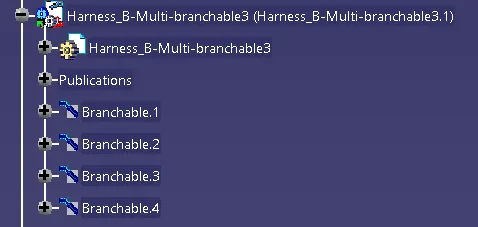
4. CAT.part of harness assembly and convert is in. igs format.
-click on tools in the mechanical assembly workbench.
-Select Generate CADPart from product
-Select the product.