Wiring harness design in CATIA V5 - 3D modeling Week 5 & 6 Challenge
OBJECTIVE STATEMENT:
The objective of this project is to design and develop a fully routed and annotated automotive wiring harness assembly in .igs format, using the following steps:
- Route the harness layout in the Electrical workbench using the provided connectors.
- Check the bundle continuity and provide a snapshot of the result.
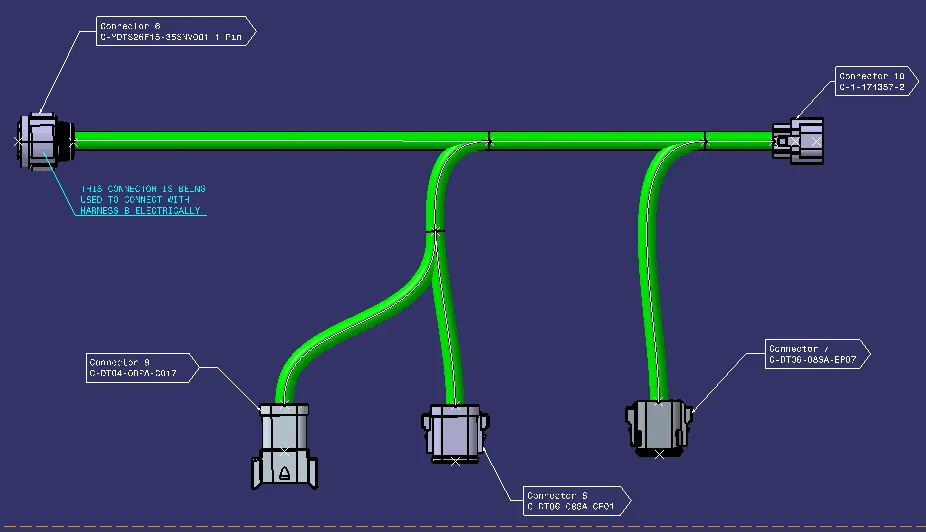
- Add annotations to all connectors using industry-standard nomenclature.
- Check for bundle warnings and provide a snapshot.
- Generate a CAT.part of the harness assembly and convert it to .igs format.
This project will demonstrate my ability to:
- Apply industry standard practices to design and route automotive wiring harnesses.
- Utilize the Electrical workbench to perform bundle continuity and warning checks.
- Add annotations to connectors in accordance with industry standards.
- Generate CAT.parts and convert them to .igs format for downstream manufacturing and documentation.
The successful completion of this project will result in a deliverable that meets all customer requirements and is ready for production.
HARNESS LAYOUT:
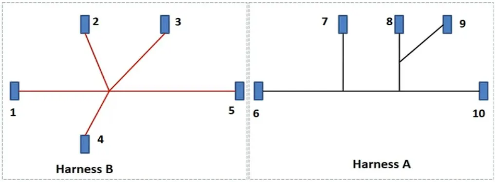
CONNECTORS PROVIDED FOR HARNESS A:
1. DT04-08PC-CE01 (FEMALE CONNECTOR)
2. DTS26F15-35SNV001.1
3. C-1-174357-2.1
4. DT06-08SA-CE01
5. DT06-08SA-EP07.1
CONNECTORS PROVIDED FOR HARNESS B:
1. DT06-08SA-CE13.1 (MALE CONNECTOR)
2. DTS26F15-35SNV001.1
3. DT06-3S-CP01.1
4. DT06-08SA-CE04.1
5. DT06-08SA-EP07.1
HARNESS A:
First, we'll define each connector in the Electrical Part Design Workbench:
1. Create the required geometrical features, which are branching points at the mating side and bundle entry side.
2. Use the Define Connector command in the Electrical Device Definition toolbar to define the geometrical features as connectors.
3. At the desired locations, define the Bundle Connection Point and Connector Connection Point.
Once the connectors are electrically defined, they can be used in the Assembly Design Workbench to create a wiring harness assembly. To do this, follow these steps:
1. Create a sketch with respect to one of the connectors.
2. Use the Snap feature to align and place the rest of the connectors at their intended locations.
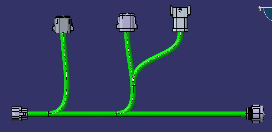
The Electrical Wiring Harness Assembly Workbench in CATIA V5 is used to define the geometric bundle that links the various connection points of an electrical wiring harness. This workbench allows us to create and manage the bundle segments, which are the individual wires that make up the harness.
DEFINING THE PRODUCT AS GEOMETRICAL BUNDLE:
To create a Harness Assembly Product we must first define the product as Geometrical Bundle. This can be done using the Geometrical Bundle command under the Creation toolbar.
Once we have defined the product as a Geometrical Bundle, we can use the Multi Branchable Document command to switch to the Wiring Harness Installation Workbench. This workbench is used to define the routing of the bundle segments.
DEFINING BUNDLE SEGMENTS:
To define a bundle segment, we must first create a Branch Definition. This can be done using the Branch Definition command under the General toolbar.
In the Branch Definition dialogue box, we must specify the following:
Bundle Diameter: The diameter of the bundle segment.
Bend Radius Ratio/Length: The bend radius ratio is the ratio of the minimum allowable bend radius to the bundle diameter. For example, a bend radius ratio of 1.4 means that the minimum allowable bend radius is 40% more than the bundle diameter.
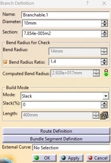
Once we have specified the Branch Definition, we can use the Route Definition command to create the bundle segment.
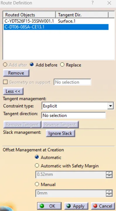
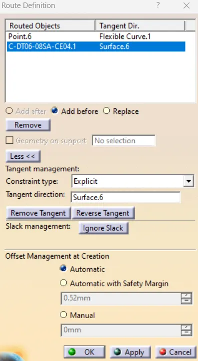
In the Route Definition dialogue box, we must select the connectors that we want to route together. we can also use the Tangent Management option to shape the bundle segment into the desired shape by changing the tangent direction or changing the constraint type from 'Explicit' to 'From Curve' but in our case, we won't need to do that since we'll get our desired bundle segment just by altering the tangent direction whenever required.
CREATING SUB-BRANCHES:
To create a sub-branch of the harness, we can use the Add Branch Point command. This command will create a branch point at the selected location.
Once we have created a branch point, we can use the Branch Definition and Route Definition dialogue boxes to define the sub-branch.
For the main branch of the harness, we should use a bundle segment diameter of 10mm and a bend radius ratio of 1.4. This means that the minimum allowable bend radius for the main branch will be 14mm.
For all other sub-branches, we should use a bundle segment diameter of 5mm and a bend radius ratio of 1.4. This means that the minimum allowable bend radius for the sub-branches will be 7.5mm.
HARNESS B:
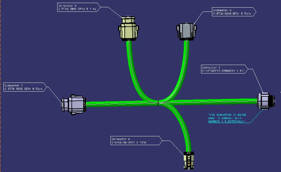
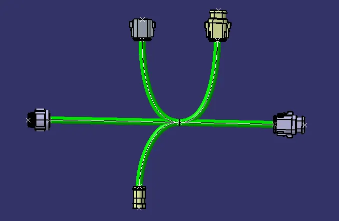
We're going to repeat these previous steps for our second harness layout called 'Harness B' as shown below:
BUNDLE CONTINUITY CHECK:
HARNESS A:
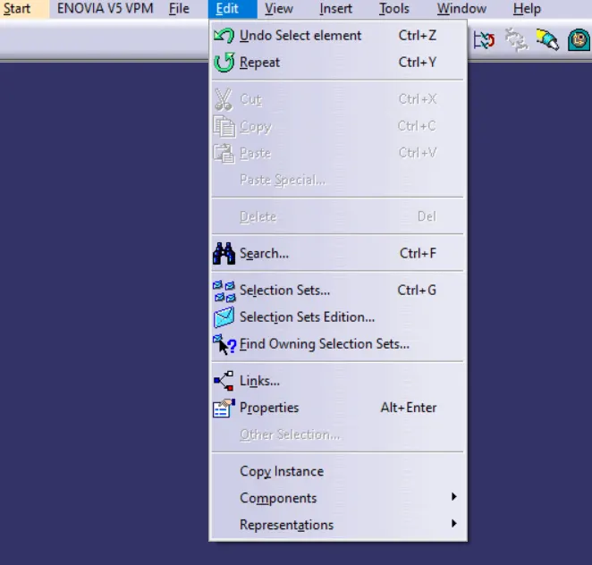
To check if our Bundle Segment is connected in the correct manner and ensure that there are no loose connections, we're going to go under the 'Search' option under 'Edit' as shown below:
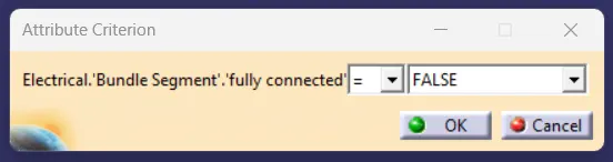
In the 'Search' dialogue box, we'll go under the 'Advanced' section, choose our workbench as 'Electrical', We'll choose 'Type' as 'Bundle Segment' and under 'Attribute' we'll choose 'Fully Connected' which will open up another dialogue box for us named as 'Attribute Criterion' where we'll choose the condition initially as 'True' and later as 'False'.
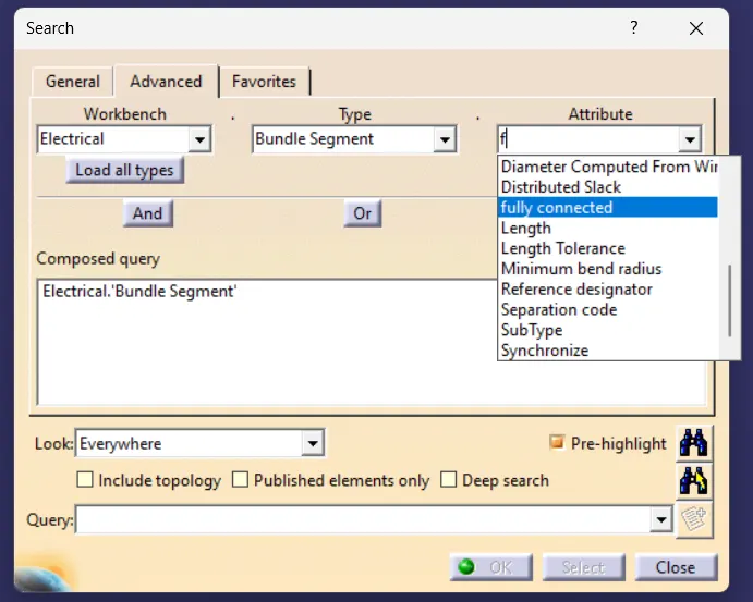
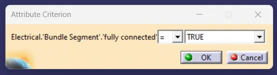
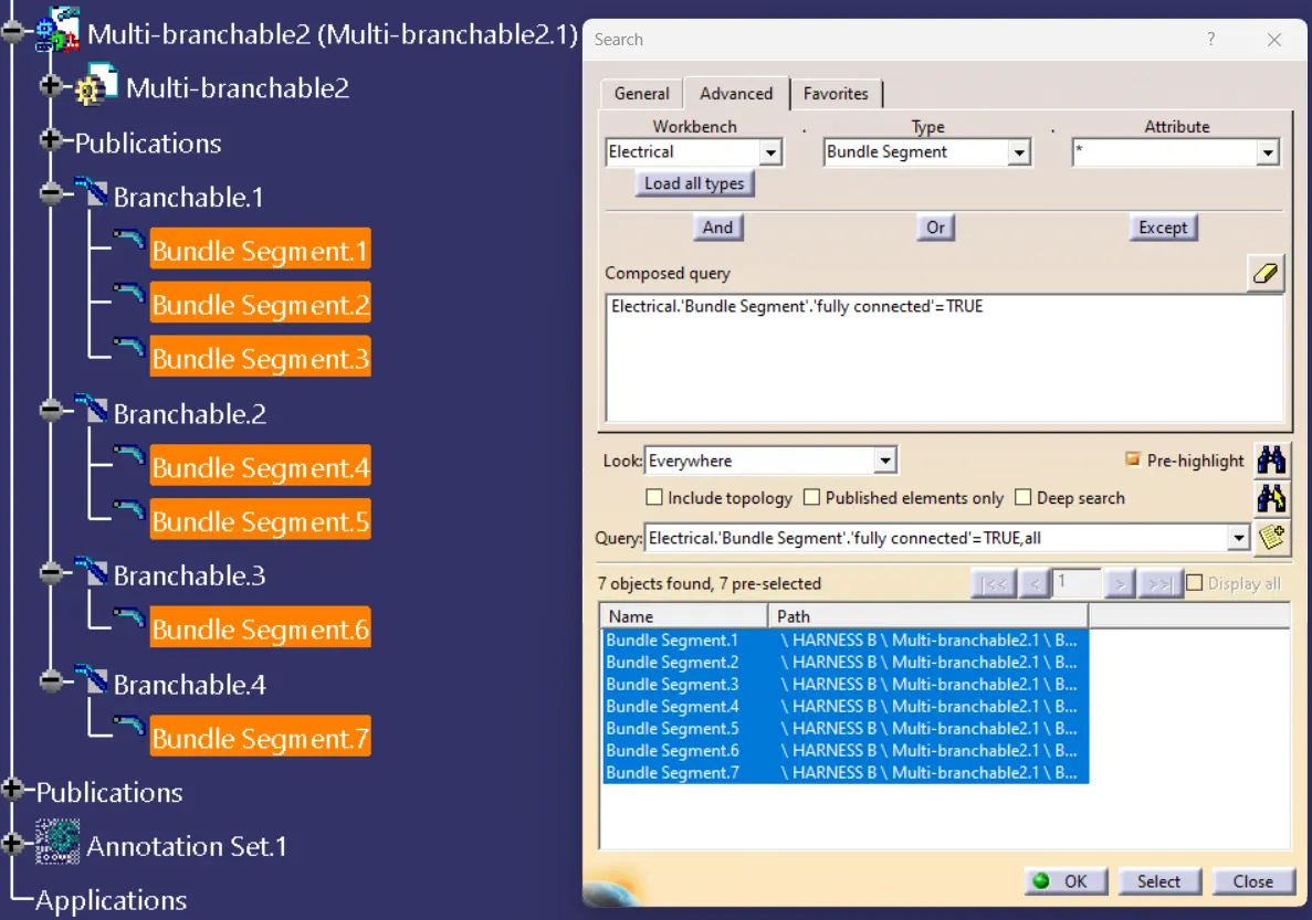
After choosing our attribute as 'True' if we click on the search button below, CATIA will inspect our Bundle Segment and see if all of our branches are connected or not.
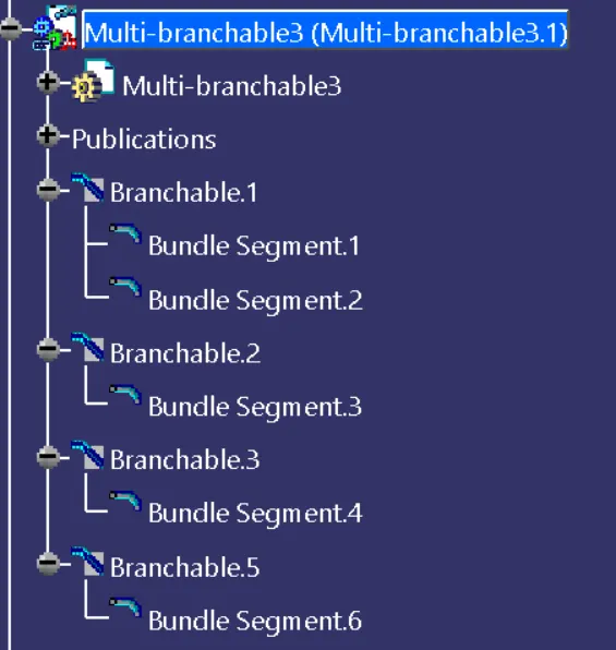
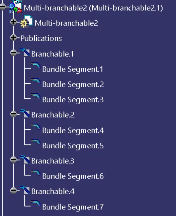
Our Multi Branchable Segment for Harness A under the Specification Tree:
Results after Bundle Continuity Check using the 'Search' tool:
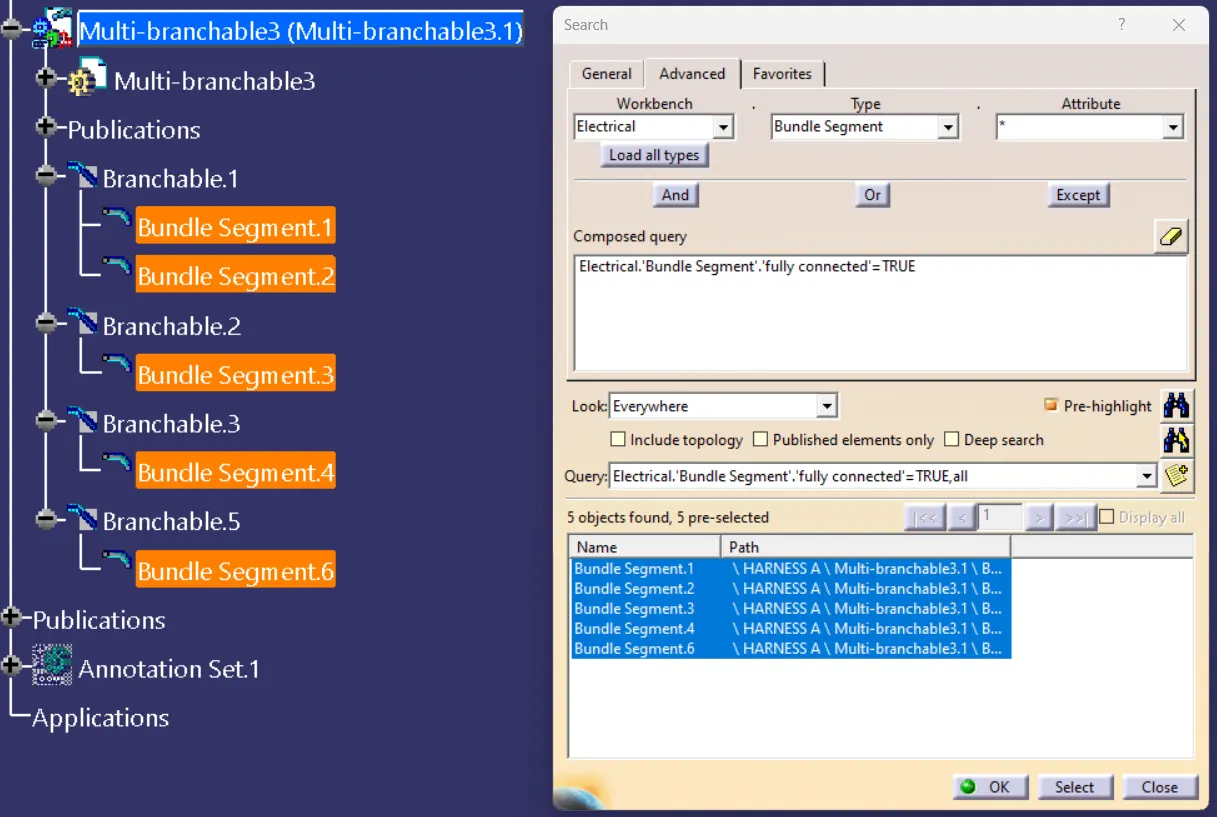
If we choose our 'Attribute Criterion' as false and click on 'Search' then it'll show us if there's any bundle segment that is not connected to our bundle segment.
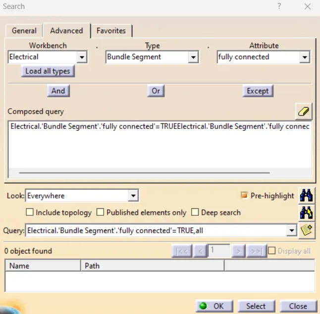
From the above image, we can notice that none of the names of our branches from the Bundle Segment for Harness A has appeared as being not connected with our bundle segment which means all of these connectors are fully connected with each other.
HARNESS B:
When the attribute criterion is 'True'
When the attribute criterion is 'False'
So, we can conclude that all of our connectors are fully connected with each other and there's no discontinuity between them at any point.
CONNECTING HARNESS A & B WITH EACH OTHER ELECTRICALLY:
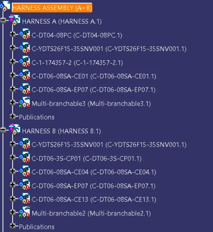
Now, we're going to connect both of our harnesses together. Firstly, we'll create a new product file in CATIA and import both of our harnesses inside it using the import existing component command present in the Assembly Workbench.
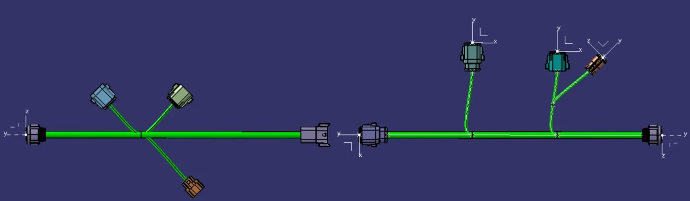
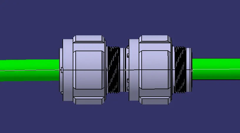
Then we're going to align them with each other according to the layout that was provided to us. We're going to use the 'Snap' command from the 'Move' toolbar from that workbench to align the mating male and female connectors with each other as shown in the images below:
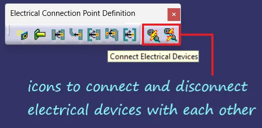
Now, to connect both of these harnesses electronically, we're going to move on to the Electrical Assembly Design Workbench and use the command 'Connect Electrical Devices' from the Electrical Connection Point Definition toolbar as shown in the image below:
Now, we're going to click on the respective female connector of Harness A that we're going to connect with the male connector of Harness B. After the initial click on the first connector belonging to Harness A, we'll notice that CATIA will automatically suggest us the there's a connection point available at the opposite male connector from Harness B.
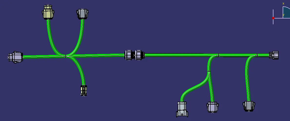
The moment we click on the connector of Harness B, both of these connectors will get connected with each other electrically using various constraints as shown below:
ANNOTATIONS:
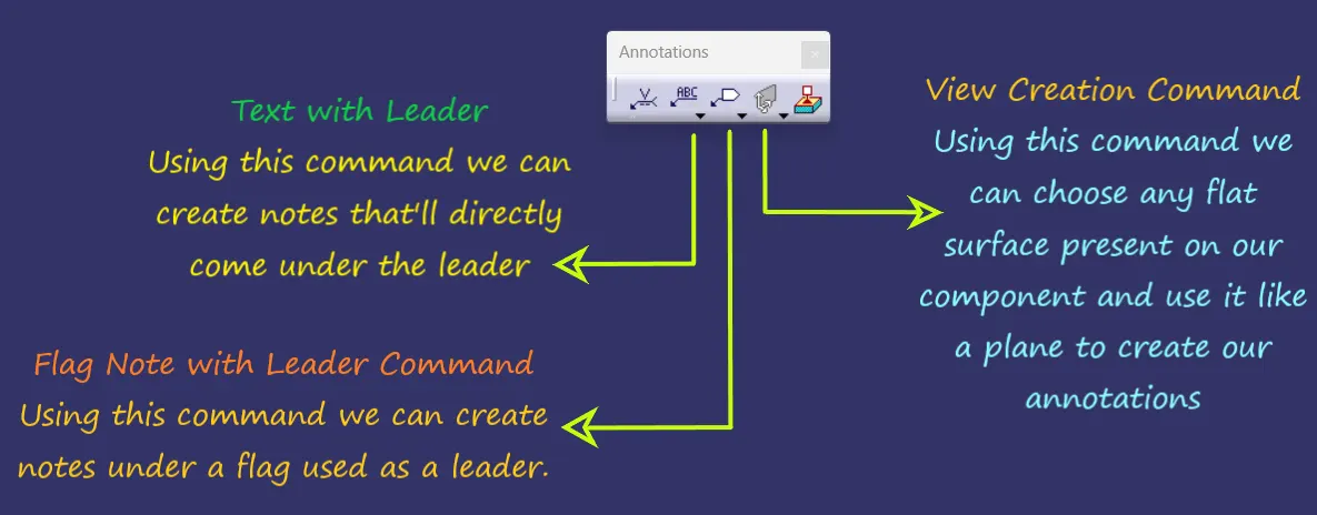
The Annotations command in CATIA V5 Assembly Workbench allows you to add text, symbols, and other annotations to your assemblies. This can be useful for documenting your design, providing instructions for assembly, or identifying important features.
ANNOTATIONS FOR HARNESS A:
ANNOTATIONS FOR HARNESS B: