Wiring harness design in CATIA V5 - 3D modeling Week 5 & 6 Challenge
WIRING HARNESS ROUTING
Aim:
The aim of the project is to study and understand the given harness layout and by following the layout and design guidelines create two different wiring harness routing set and finally interconnected them by adding it into anew product file using the Catia V5 tool.
Introduction:
Wiring Harness Design and Routing:
Wire Harness are a mixture of wires that are bundled together to form a wire harness.Wire harnesses range in complexity from a few individual wires going point to point hundreds of individual wires,multi conductor cables and welded wires all forming a complex wire harness used to transmit power and all types of data.Wire harness designs are highly customizable ,as harness are typically designed to suit specific applications.They may need to be concealed behind walls,fit within electrical boxes,or conform to other space constrints.Precise measurements of the environment,power demand and lengths must be taken during design to prevent costly mistakes and ensure proper safety and functionality of the final product.
A wiring Harness Routing structure includes a wiring harness routing member configured to be attached to a vehicle body and a protector that accommodates and holds a wiring harness.The protector has a recess shape in which the protector is opened in one direction in a sectional view.At least one of the wiring harness routing members and the protector includes a fixing mechanism that fixes the protector that fixes that protector to the wiring harness routing member.the protector and the wiring harness routing member are configured to be integrated via the fixing mechanism.
INPUT WIRING HARNESS LAYOUT:
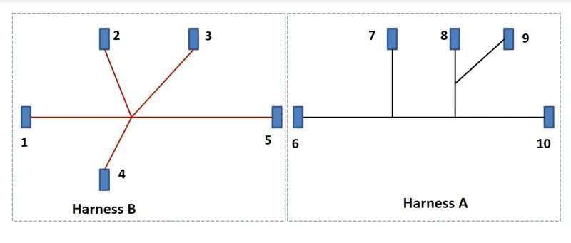
Steps to be followed for Routing the Wiring Harness A and B:
- Download all the stp file and igs file of the connectors from the given source.
- Then Define the connectors in the connector connection point and bundle connection point and define as the electrically defined.
- Save the connectors in the required folder.
- Open the Catia V5 by using Electrical Assembly Design and create the new product and click on the existing components and import the electrically Defined Connectors and arrange the connectors in positions of the wiring Harness layout of harness A and harness B.
Creating Wiring Harness assembly A with reference to the given layout:
- Create a new product file for wiring harness assembly A and the relevant components to the product file.
- Convert the geometrical bundle assembly file of A into an electrical bundle.
- Applying Routing to the wiring Harness assembly A by adding bundles to the wiring harness assembly.
- Wiring harness assembly of A after routing.
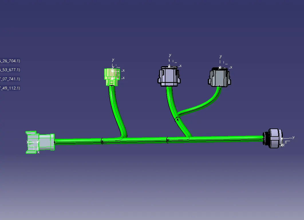
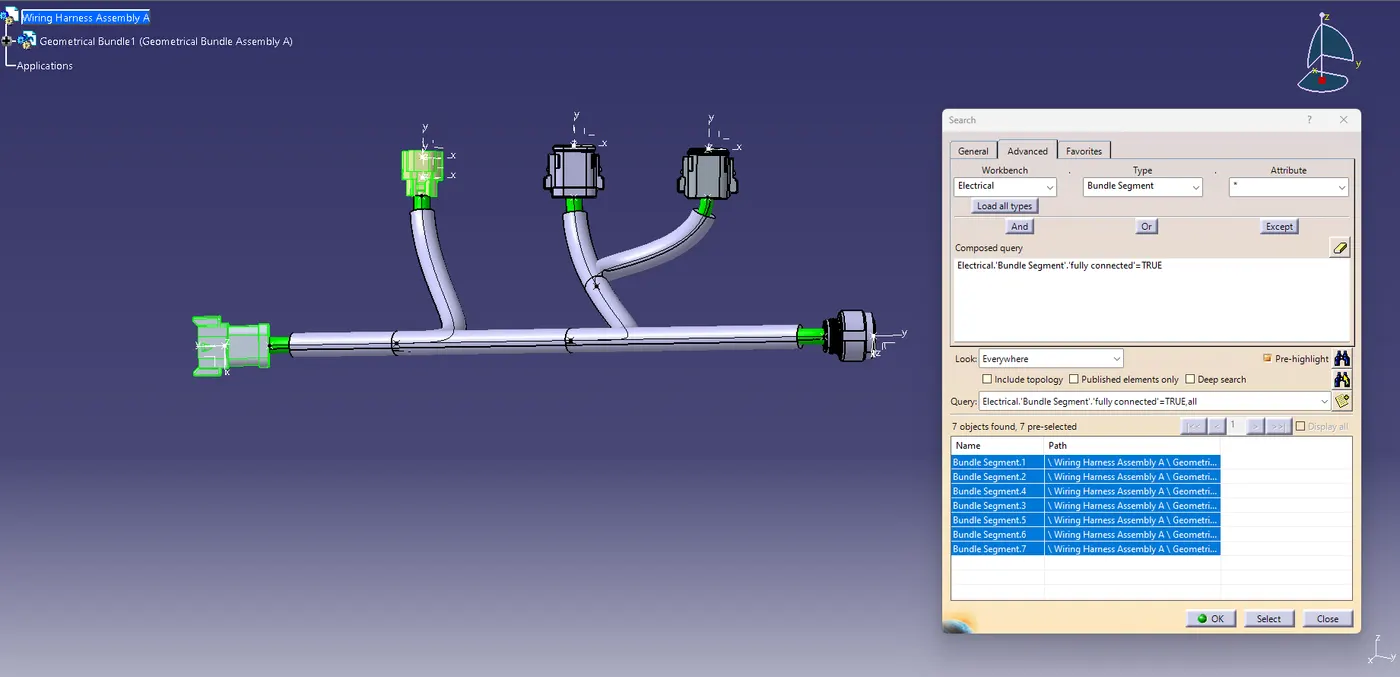
Check for the bundle contintuity in the wirinh harness assembly A,
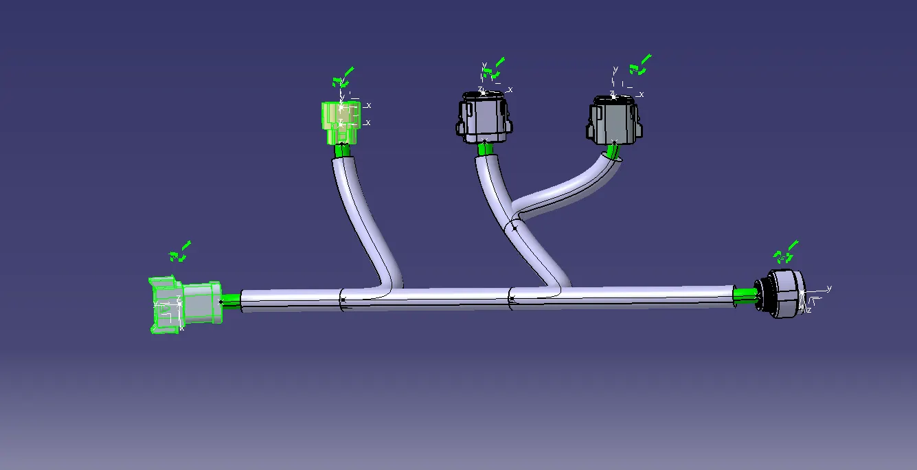
Adding Annotations to the wiring harness assembly A,
Creating Wiring harness assmebly B with reference to the given layout:
- Create a new product file for the wiring harness assembly B and add the relevant components to the product file of B.
- Convert the geometrical bundle assembly file of B into an electrical bundle.
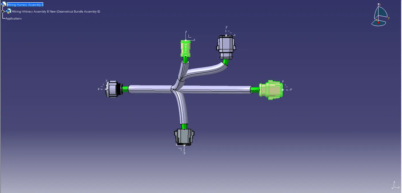
- Applying routing to the wiring harness assembly B by adding bundles to the wiring harness assembly of B.
- Wiring Harness assembly B after routing.
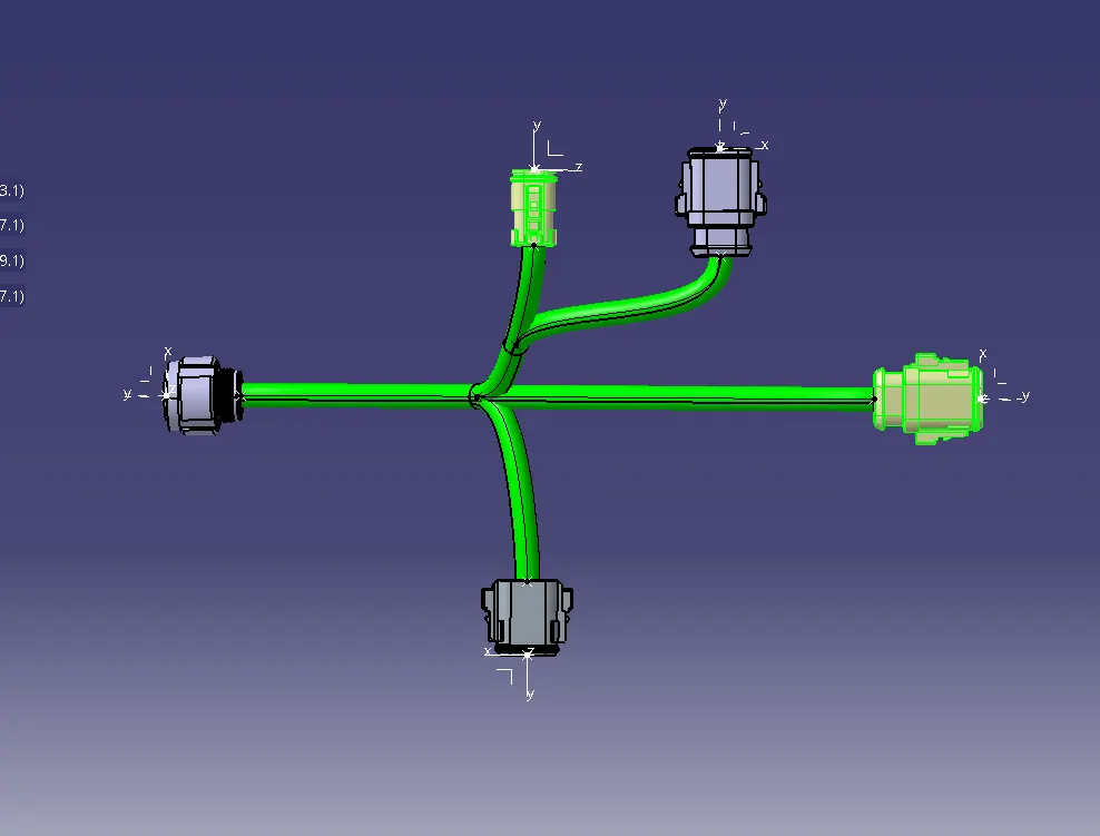
Check the bundle Continuity in the wiring harness assembly of B,
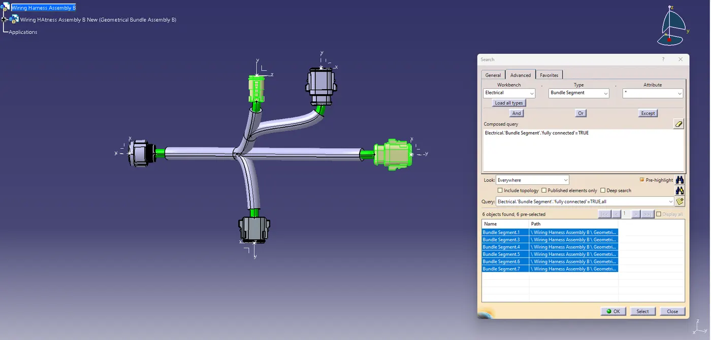
Adding the annotations to the wiring harness Assembly B.

Interconneting the wiring Harness assemblies of A and B:
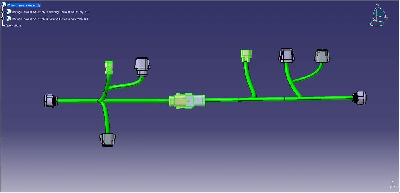
Connecting two sets of wiring harness assembly.
Adding protective Covering For Wiring Harness A and B:
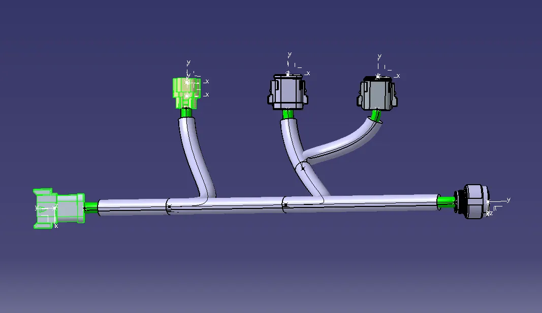
Conclusion:
The given mechanical part files of the connector are converted into the electrical part file then add relevant connectors to the new product files and routed the assembly by adding bundles,and positioning the connectors in an appropriate location as per the layout.Check for the connectivity of the bundles and resolve the errors.Give proper annotations to each assembly as per the layout and inter connected the assemblies by adding them to a new product file.The final assembly file is then converted into a CAT part and create an igs file for the same.Thus understanding how to develop the routing with reference to the given layout and the process of joining two sets of wiring harness assemblies.