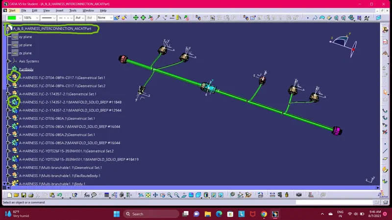
Wiring harness design in CATIA V5 - 3D modeling Week 5 & 6 Challenge
Wiring harness design in CATIA V5 - 3D modeling Week 5 & 6 Challenge
1). Check the bundle Continuity. Add snap of result in submission?
Ans). The bundle continuity define bundles are fully connectedt to each other properly throuhgout the start to end.
Steps to Check the bundle Continuity:
- After creation of electrical bundle assembly in electical harness assembly workbench make sure multi-branchable activate and then move the cursor to left top side then click on 'Edit' command. As shown in below image.

- Then select the 'Search Option' in search option select the 'Advance' option. As shown in below images.


Then select the 'Workbench' in workbech list select the 'Electrical'. As shown in below image.
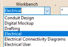
Then select the 'Type' in type list select the 'Bundle Segment'. As shown in below image.

Then select the 'Attribute' in attribute list select the 'fully connected'. As shown in below image.
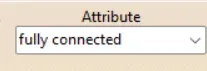
After selection of fully connected option there is attribute criterion pop on screen. There are two option available True and False options. If you select the true and by click on 'ok' button proceed. As shown in below image.
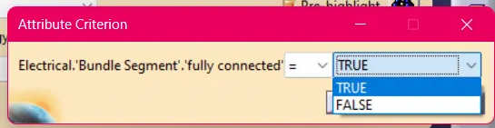
Then select search icon  after selection fully connected bundles are displayed on screen as shown in below image.
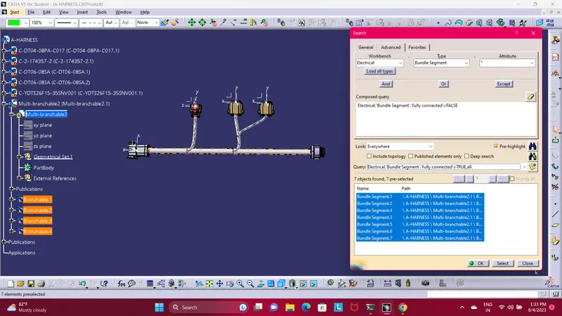
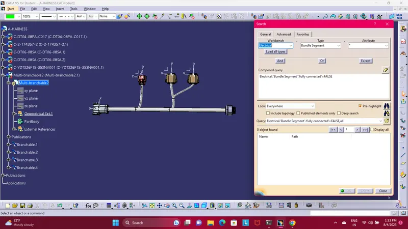
(Bundle Continuity check with True option) (Bundle Continuity check with False option)
2). Add annotation to all connectors. Make an assumptions for annotations like connect 1 , 2 etc?
Ans). My catia v5 is not allowing me to apply annotation. While applying annotation and when selecting the planar face of connector an error pop-up as shown in below image. Even uninstall the catia v5 software
and again install and try but same issue.
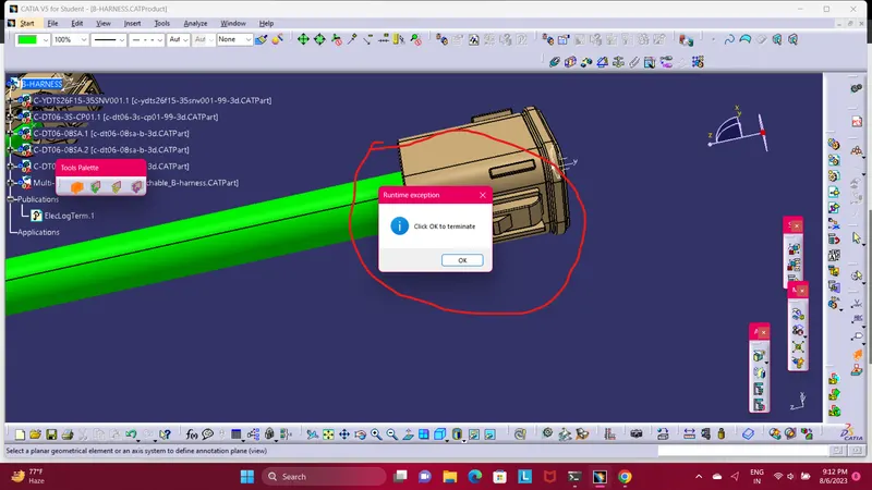
( Error pop-up while applying annotation )
3). Check for the bundle warning. Add snap.
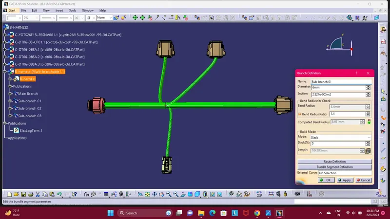
Ans). Bundle warning is the warning which warn you that your wire harness routing bundles is wrong this is because of bend radius, bundle diameter, branch point distance and vector position.
This warning are usually dispalyed in the tree structure of the wire harness geometrical bundle is there are issues yellow caution icon pop-up. As like shown in below image.
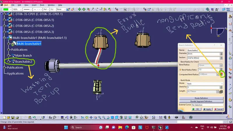
Here i solve the bundle error just repositioning the connector position and bundle diameter. You can saw the change in branch defition the computed band radius value change and it shows green indication
that means proper bundle or in above image it shows red indication.
4). Generate CAT.part of harness assembly and convert is in. igs format.
Ans). After the completion of interconnectiom wire harness assembly here i convert the electrical harness assembly product to CAT.part and save as igs format. You can saw the changes it converted to cat.part.