Wiring harness design in CATIA V5 - 3D modeling Week 5 & 6 Challenge
AIM:
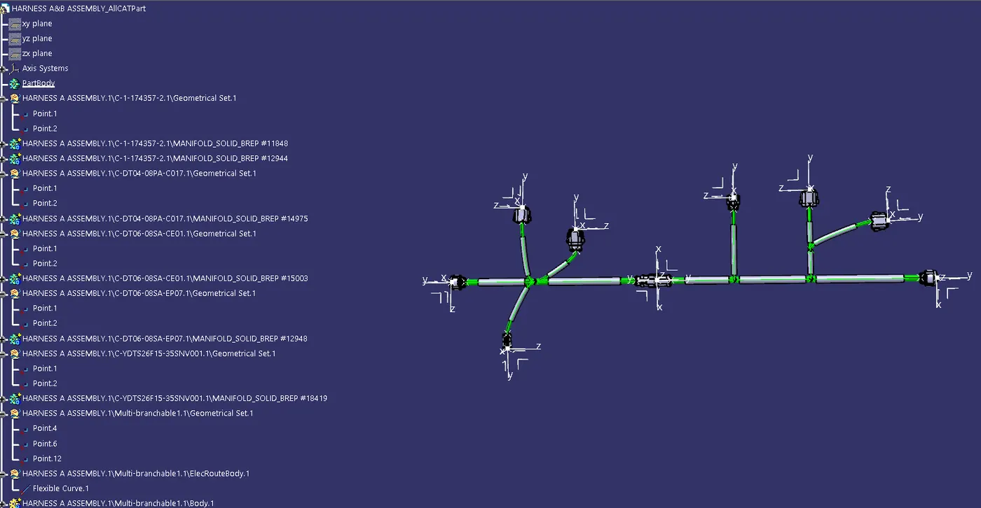
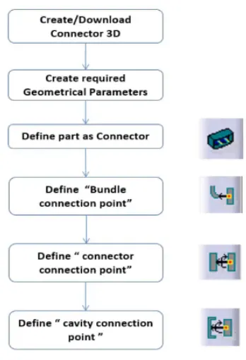
Route the following harness layout in Electrical workbench. Make assumption for harness bundle diameters. Use the connectors provided. After completion of routing,
1. Check the bundle Continuity. Add snap of result in submission
2. Add annotation to all connectors. Make an assumption for annotations like connect 1, 2 etc.
3. Check for the bundle warning. Add snap.
4. Generate CAT.part of harness assembly and convert it into .igs format.
Please find the challenge files attached in the helper file section
PROCEDURE:
1.CONNECTOR DEFINITION:
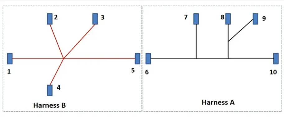
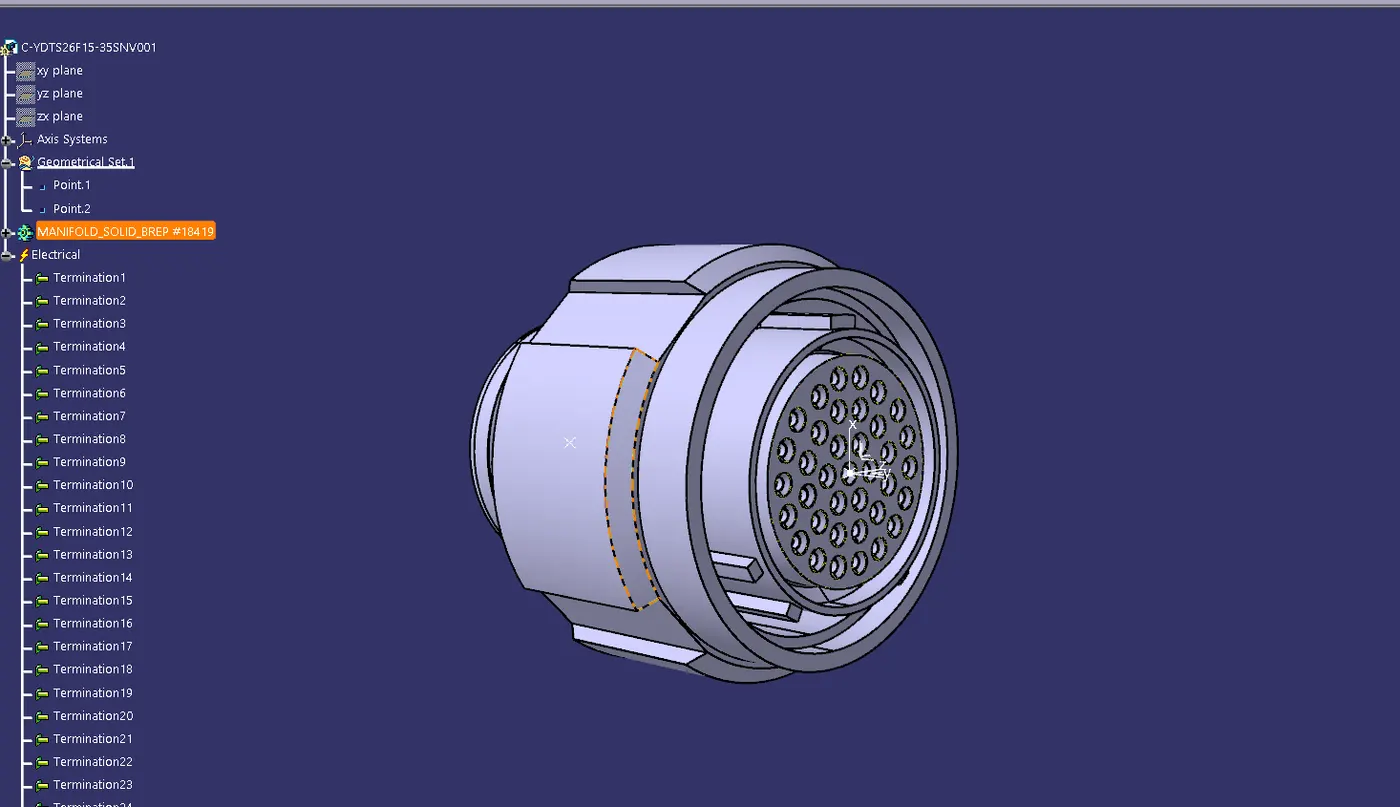
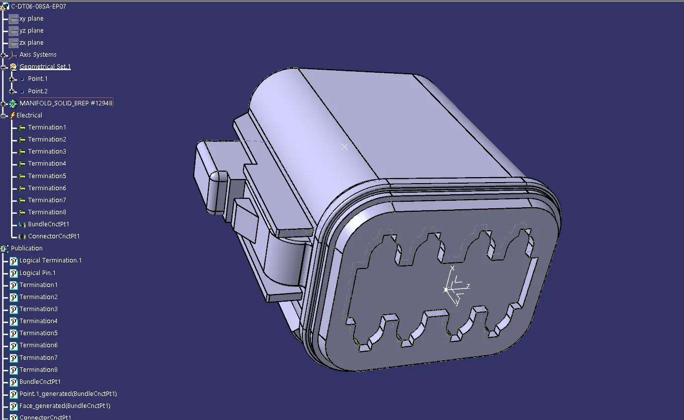
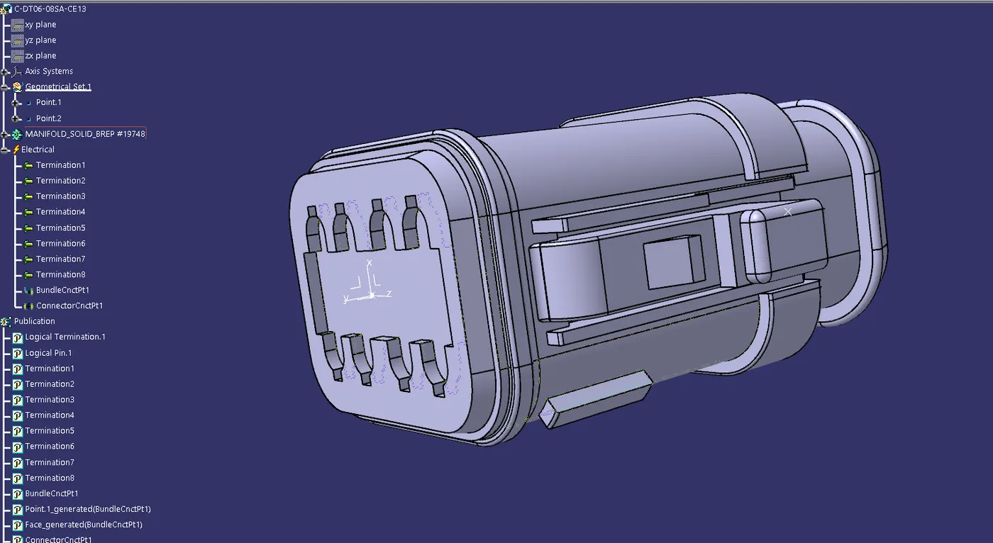
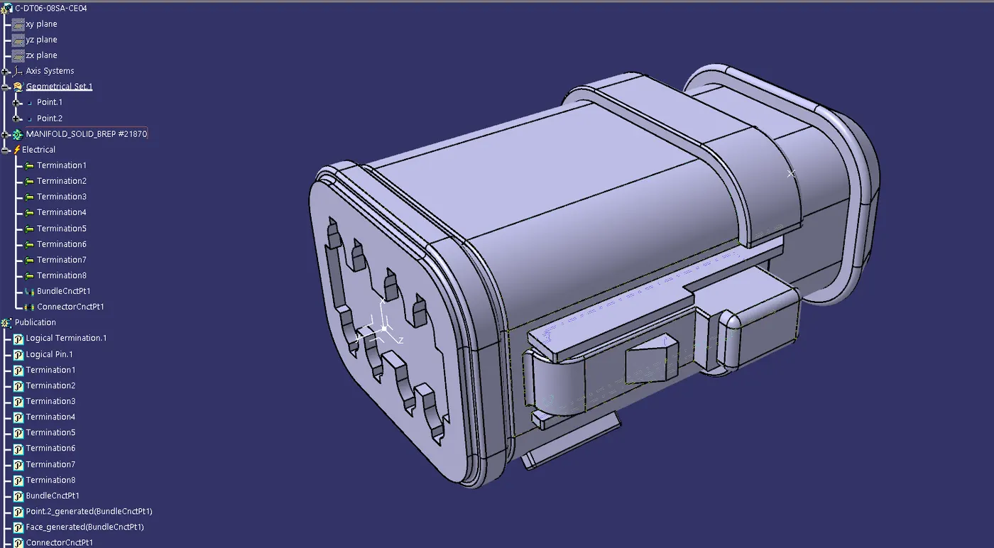
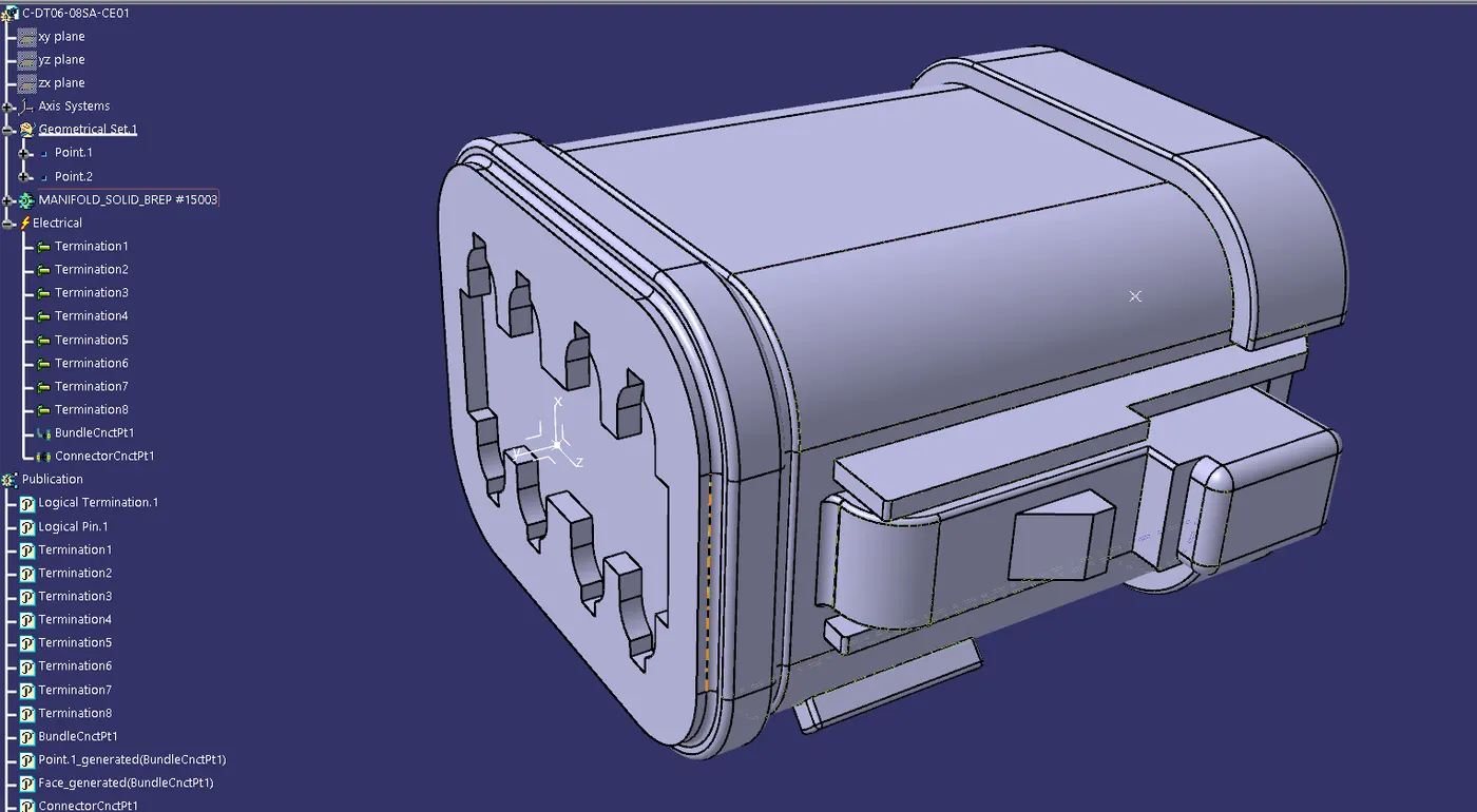
· Following Parameters are required to defined for any connector.
· Geometry Parameters - Points & Co-ordinate system (Axis)
· Connector connection points - This point is used for the connection of one connector to another connector.
· Harness bundle entry point - This point defines where the harness bundle segment point will end when routed to the electrical connector.
· Cavity connection point (Optional) - This point is used to define the connection of a connector to a connector clip. This only applies to connectors which have the mounting feature for a connector clip.
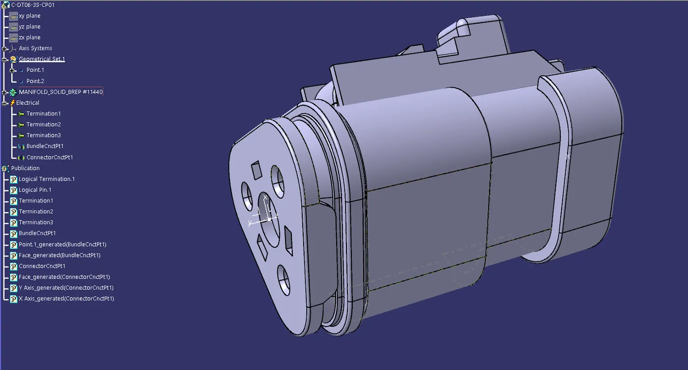
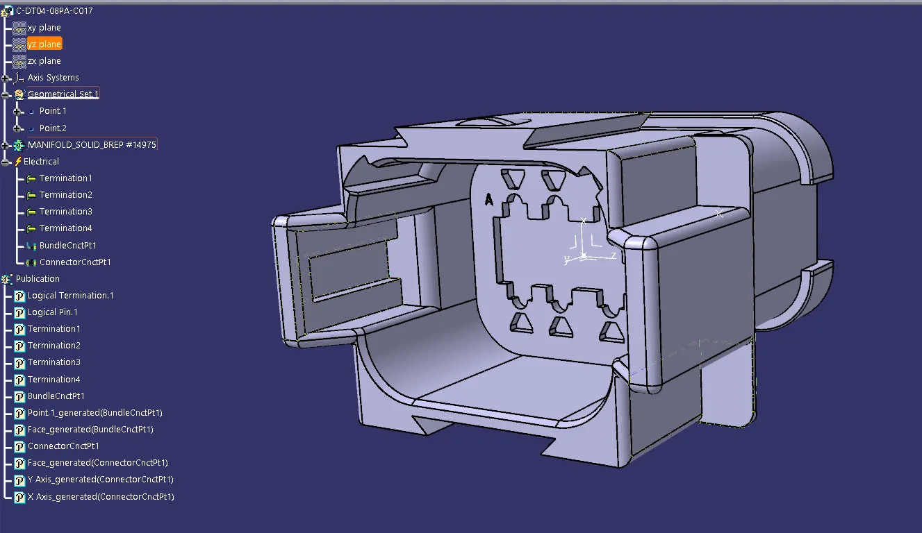
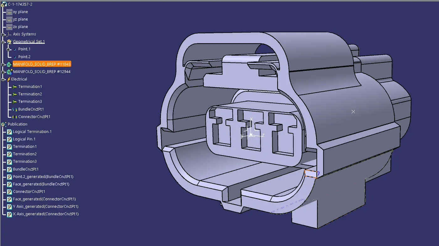
2. PRODUCT CREATION & PART POSITIONING:
· After given the electrical properties to all the connectors then start the Preparation of Harness Assembly.
· Create a master product file (HARNESS A&B ASSEMBLY) and create a sub-level product file named (HARNESS A ASSEMBLY) & (HARNESS B ASSEMBLY) and save it.
· Once Geometrical Bundle is created, then open it in a new window. Select the "Geometrical Bundle" command and then click on required Product in Model tree to convert it in to an Electrical Assembly.
· Inserting Harness Connector Components into the Geometrical Bundle. Before Inserting the components, ensure that all the required components have been electrically defined.
· Once the required components were defined electrically, then insert them using Catalogue Browser command or using existing component command.
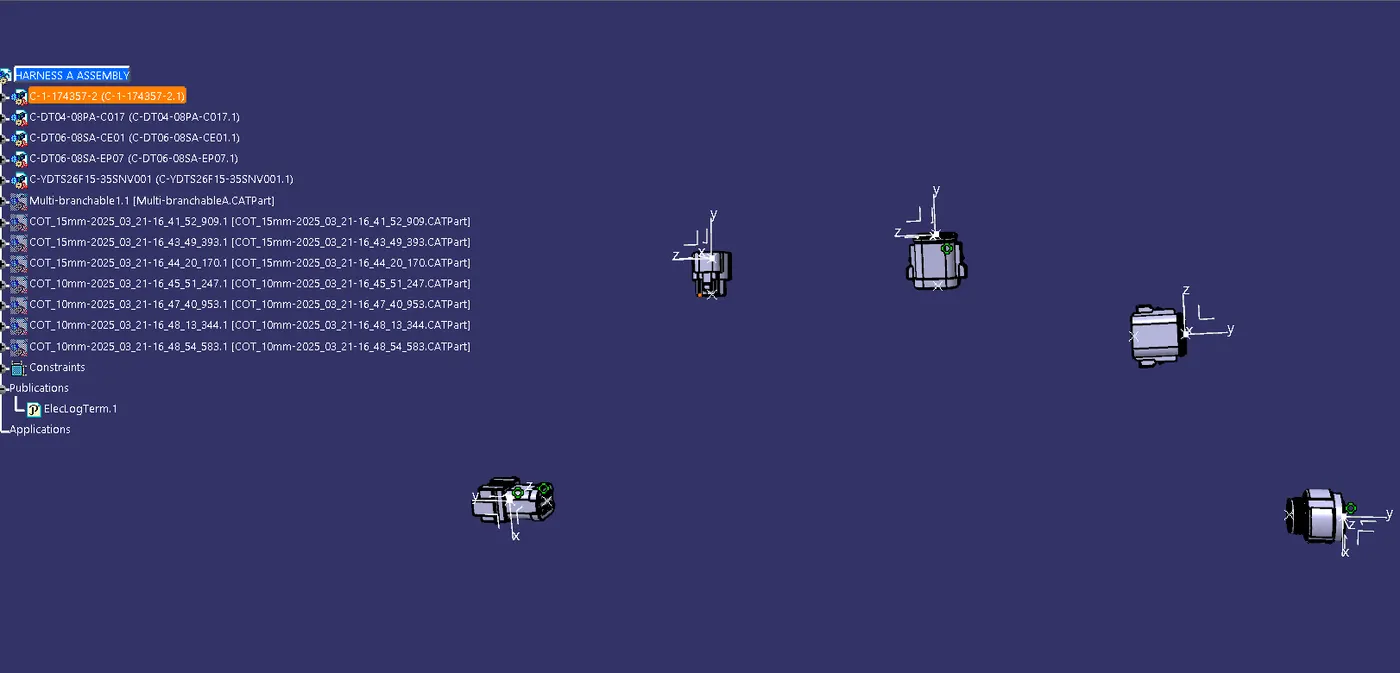
· After inserted all component position them it according to the given reference diagram. Before start routing, ensure all the components in its desired location according to surrounding data.
· If not then place and position the components by using any of the following commands like Manipulation, Translation or Rotation, Snap, Smart Move, Compass.
· If there are any assembly that need to be assembled before routing like Connector with Mounting Clip or Connector with back shell. Then Assemble them using "Connect Electrical" Devices.
HARNESS A
HARNESS B
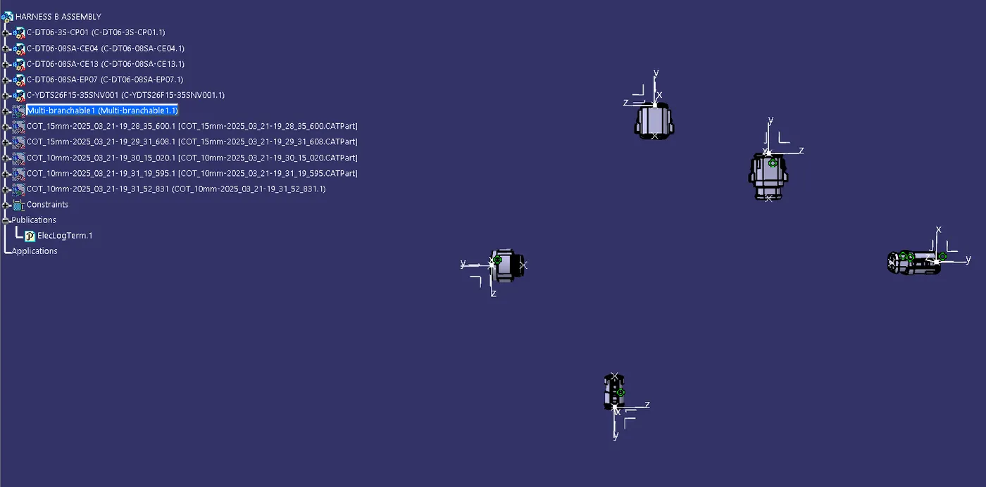
3. BRANCH CREATION:
· Switch to Electrical harness Assembly Workbench.
· Select Multi-Branchable Document Icon.
· In the Branch Definition Box (Ref Below Image), give all the required parameters like Diameter, Bend Radius (>1.4), Build mode (slack, Length, Bend, Straight Bend).
· Click Route Definition and select the two components that you need to route.
· Click OK.
· Once the multi-branchable is created, Click Add branch point command and define the point on the main branch where the Harness Branch needs to be created.
· After creating the point repeat the steps of multi-branchable creation.
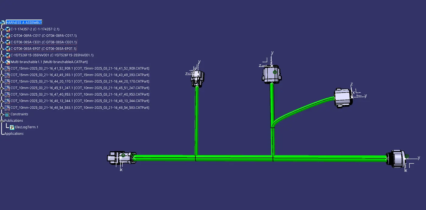

4. ADDING PROTECTIVE COVERING :
Add protective covering on the required branches by using Protective Covering Command and mention the start and end extremity points.
Switch to Electrical Harness Assembly > Select the Protective Covering > Select the Bundle Segment > Select the size of protective covering > Give its end extremity > Click OK
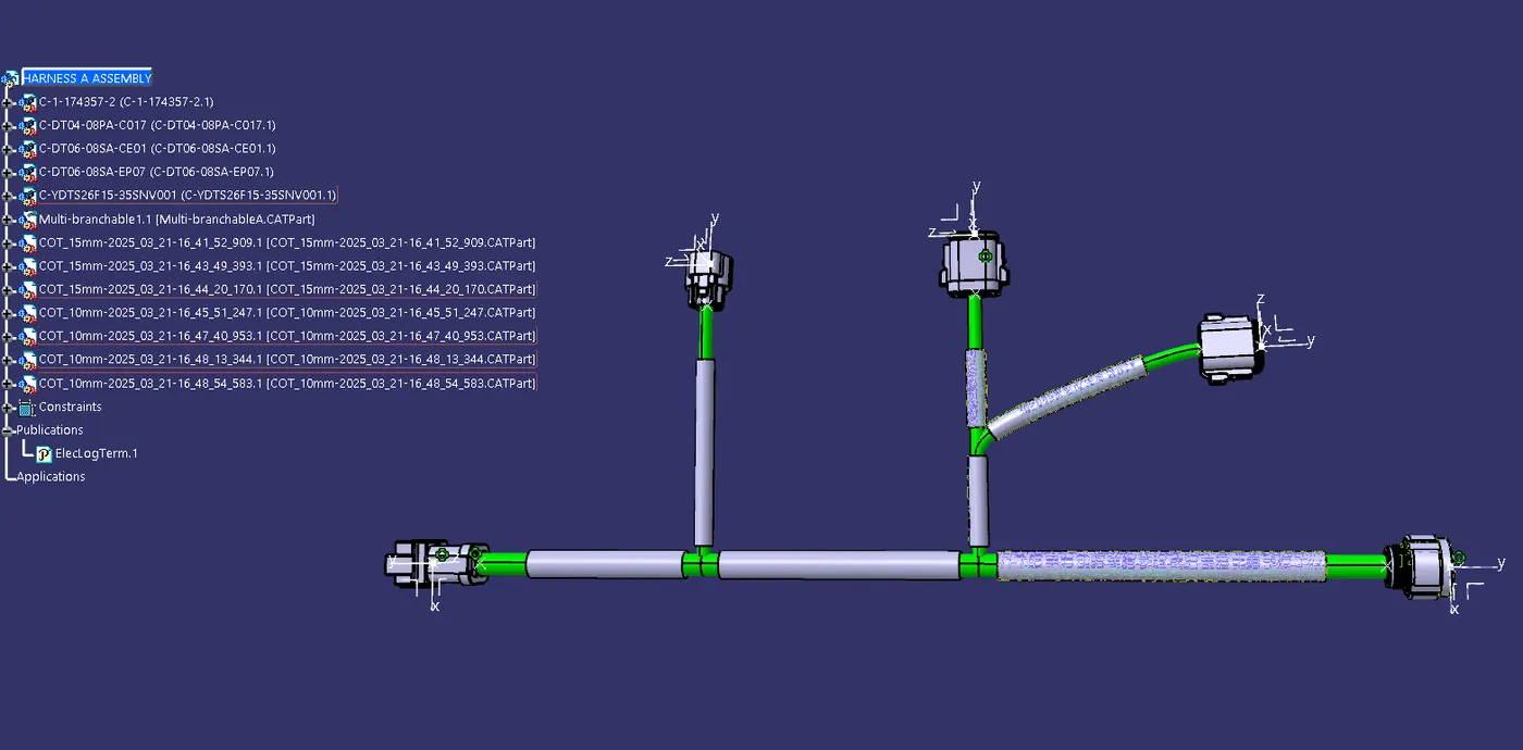
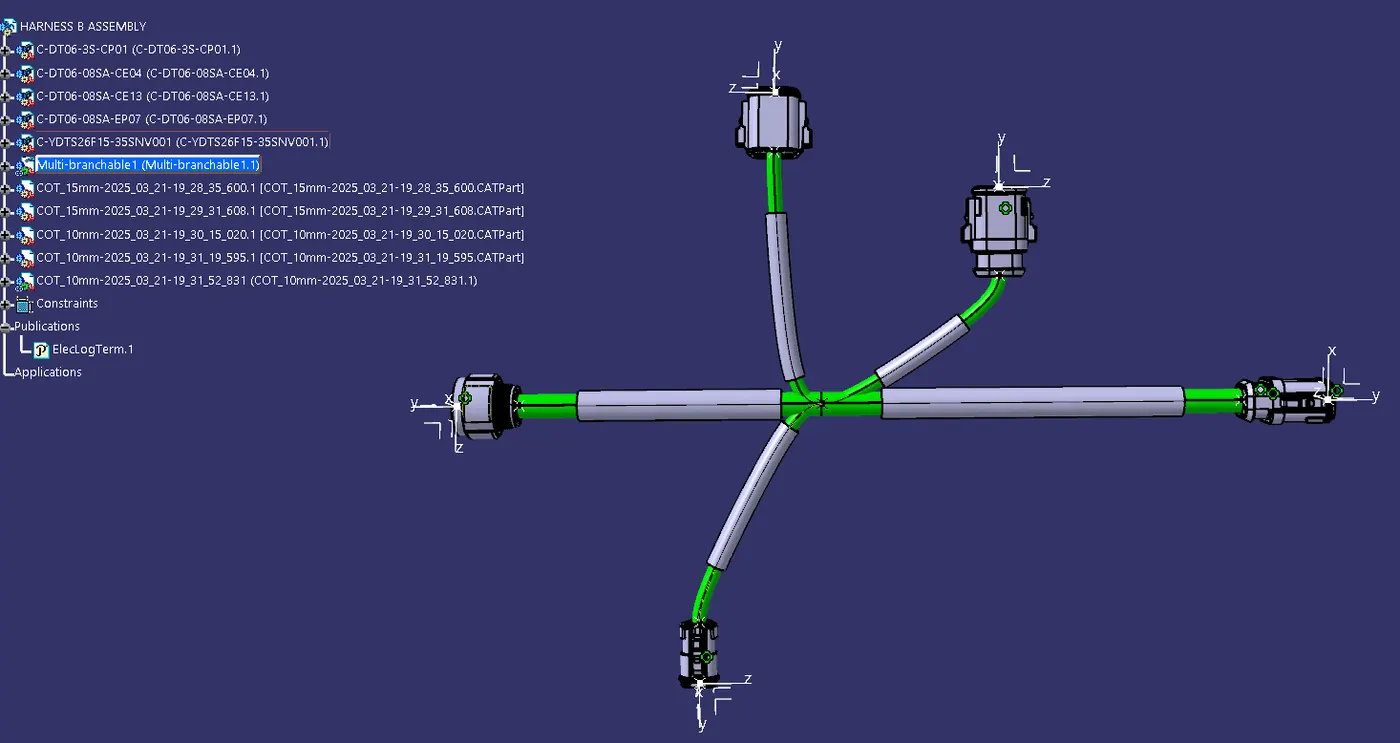
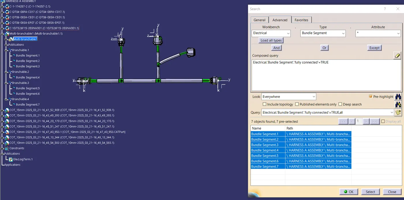
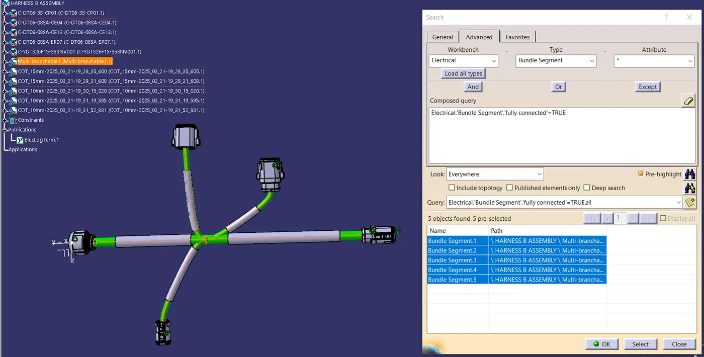
5. BUNDLE CONTINUITY TEST
· The bundle continuity needs to be examined after harness A and harness B are created.
· Then, go to Edit>Search>Advanced>Electrical Workbench>Type-Bundle Segment>Attribute-Fully Connected. Make sure multi-branchable is chosen.
· If "TRUE" is chosen, all bundle segments that are connected will be shown.
· if "FALSE," all bundle segments that are not connected will be shown.
6.ASSEMBLY OF HARNESS A & B:
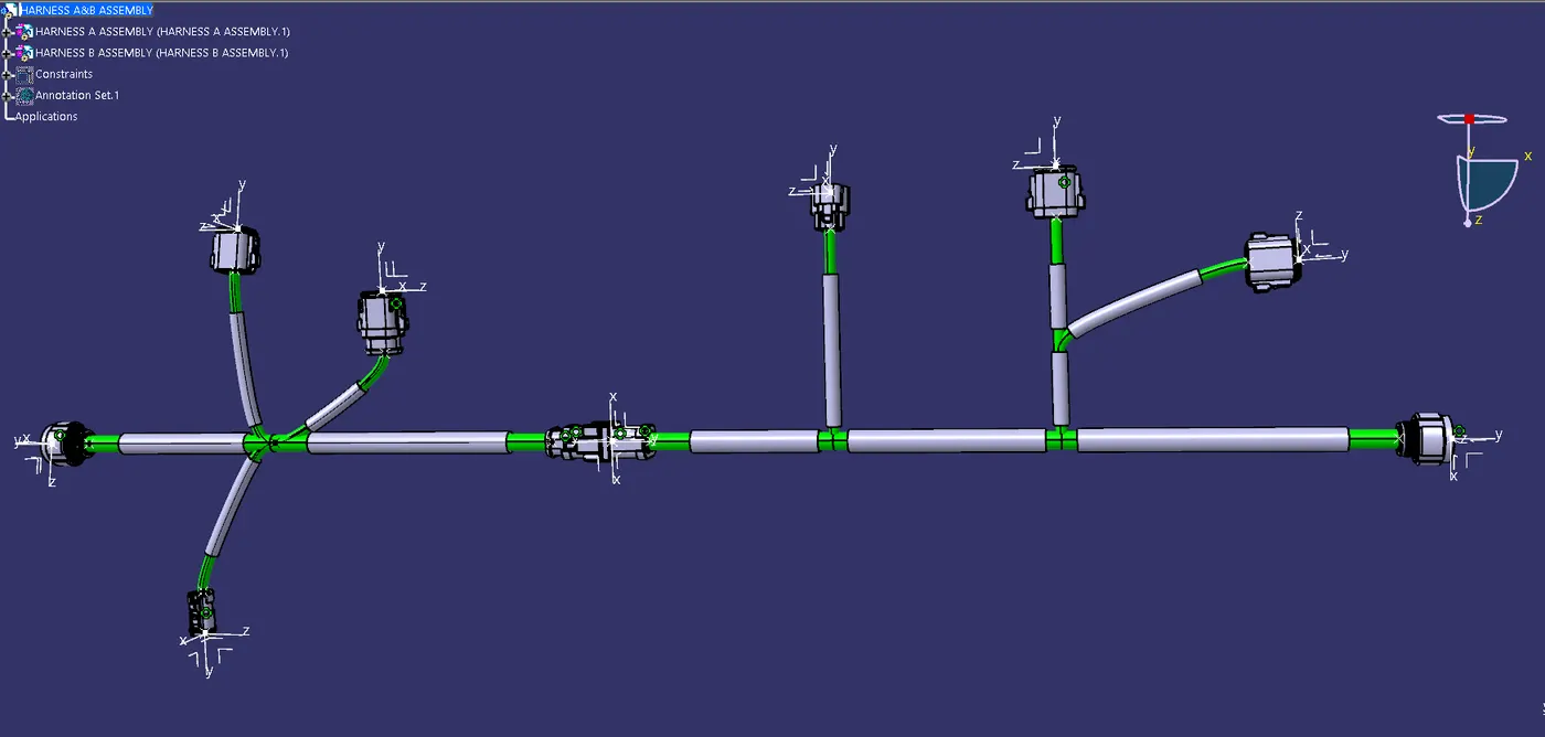
· The two harnesses need to be electrically connected, which requires a few procedures.
· Make master product (HARNESS A&B ASSEMBLY) as a work part.
· Connect the male and female connectors by using “CONNECT ELECTRIC DEVICE” option inside the electrical assembly design workbench.
7. BUNDLE WARNING ALERTS:
· We'll check Harness A and B in this phase to see if there are any bundle alerts. if a yellow flash appears in the tree structure, it reflects that there are some problems in the geometric bundle.
· We need to solve those issues by introducing slack or by modifying the vector position of the segment point, depending on the path taken by the bundle segment.
· For our case we don’t have any errors.
8. ANNOTATION
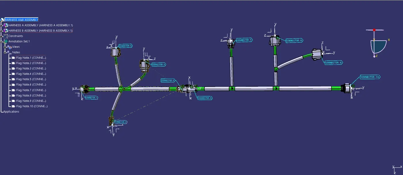
· Now to provide annotation, we will switch to assembly design workbench.
· First, we will define plane on which all annotation will be arrange
· Now we will use flag note with leader to show annotation.
9. PRODUCT TO PART CONVERSION: