Wiring harness design in CATIA V5 - 3D modeling Week 5 & 6 Challenge
Wiring harness design in CATIA V5 - 3D modeling Week 5 & 6 Challenge
Q1. Route the following harness layout in Electrical workbench. Make assumption for harness bundle diameters. Use the connectors provided. After completion of routing,
- Check the bundle Continuity. Add snap of result in submission
- Add annotation to all connectors. Make an assumptions for annotations like connect 1 , 2 etc
- Check for the bundle warning. Add snap.
- Generate CAT.part of harness assembly and convert is in. igs format.
-> HARNESS A -
First, all of the connectors need to be defined electrically and geometrically.
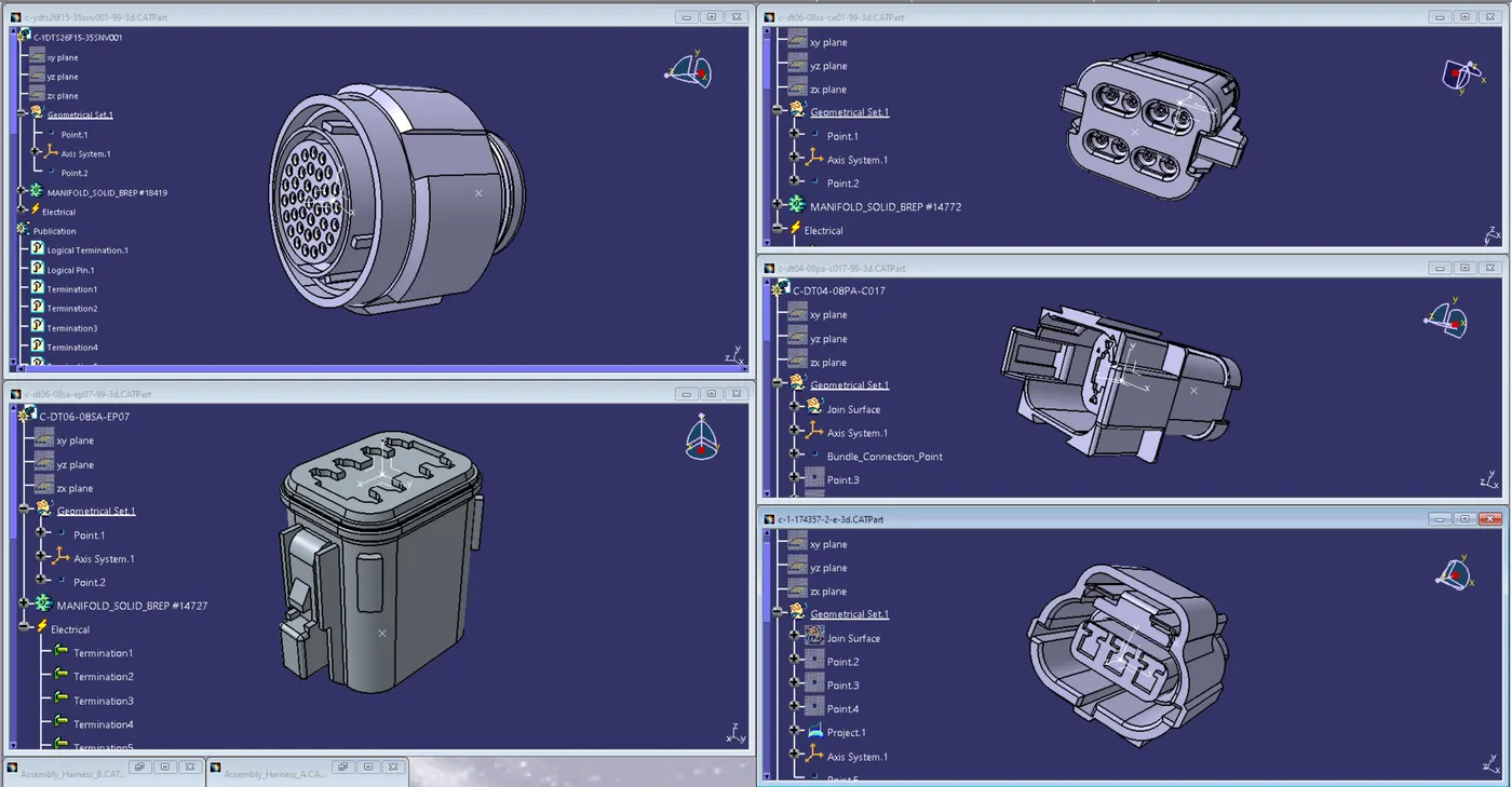
then will build the bundle section, add any required branch points, and arrange each connector in the desired location.
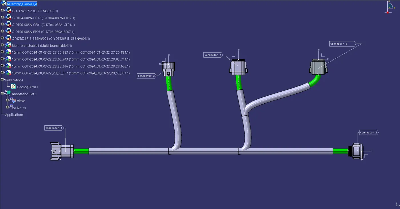
-> HARNESS - B
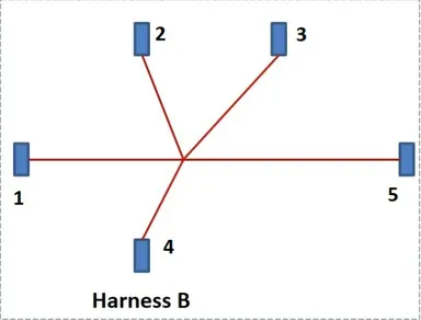
all of the connectors need to be defined electrically and geometrically.
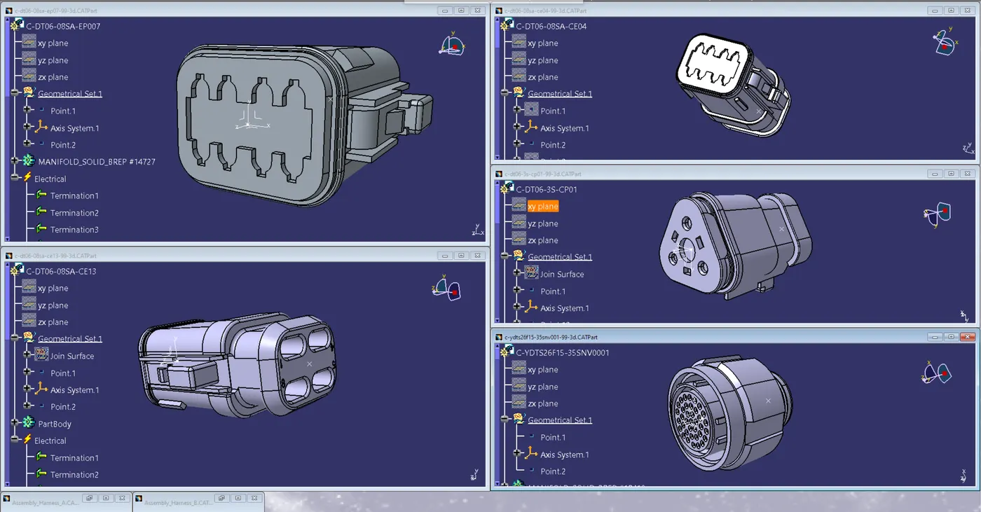
then will build the bundle section, add any required branch points, and arrange each connector in the desired location.
-> Check the bundle Continuity
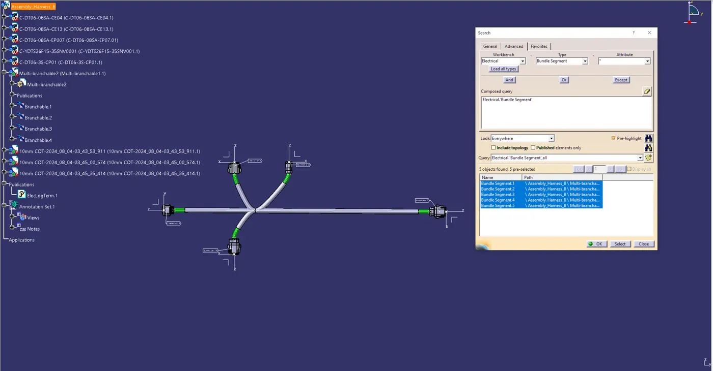
Bundle continuity needs to be verified.
Proceed to Edit>Search>Workbench-Electrical>Type-Bundle segment>Attribute-fully connected in order to accomplish that.
There will be a single window that displays all connected bundle segments when the True option is selected and all non-connected bundle segments when the False option is selected.
Let will now look for a result and verify if the condition is true.
Every bundle segment appears to be connected. Thus, bundle continuity exists.
-> BUNDLE WARNING
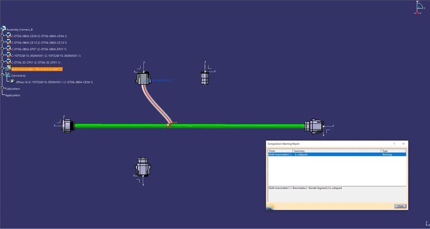
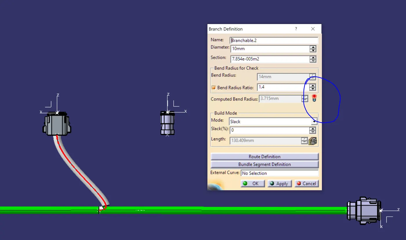
It's going to examine the bundle warning.
For bend radius, bundle diameter, and vector position, geometrical bundle warnings are displayed.
Therefore, in the model tree structure, a yellow colored flash will emerge next to the branchable with issues if there is any inaccurate value or input relating these parameters.
There is one mistake here.
The 'Reverse Tangent' option must be selected in order to rectify this problem and eliminate the yellow flash.
-> ANNOTATIONS
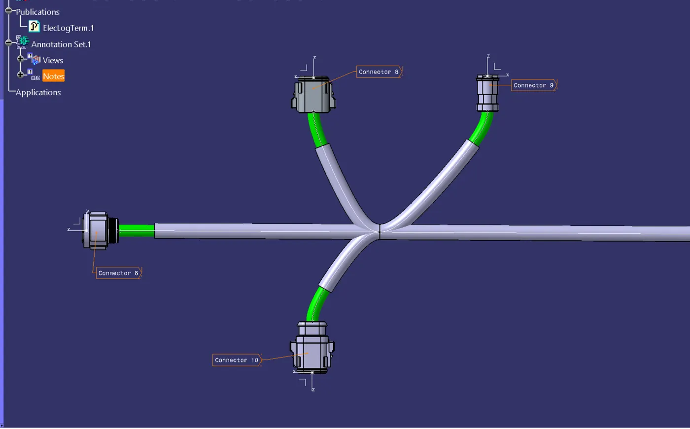
All of the connectors on the mechanical assembly design workbench require annotations.
The name, functions, etc. of the connector are provided by annotations.
The plane on which the annotation will be placed must be chosen for this. Front plane is the option we have chosen.
First, we should choose the annotation plane only after confirming that the geometrical bundle is active.
-> INTERCONNECTION
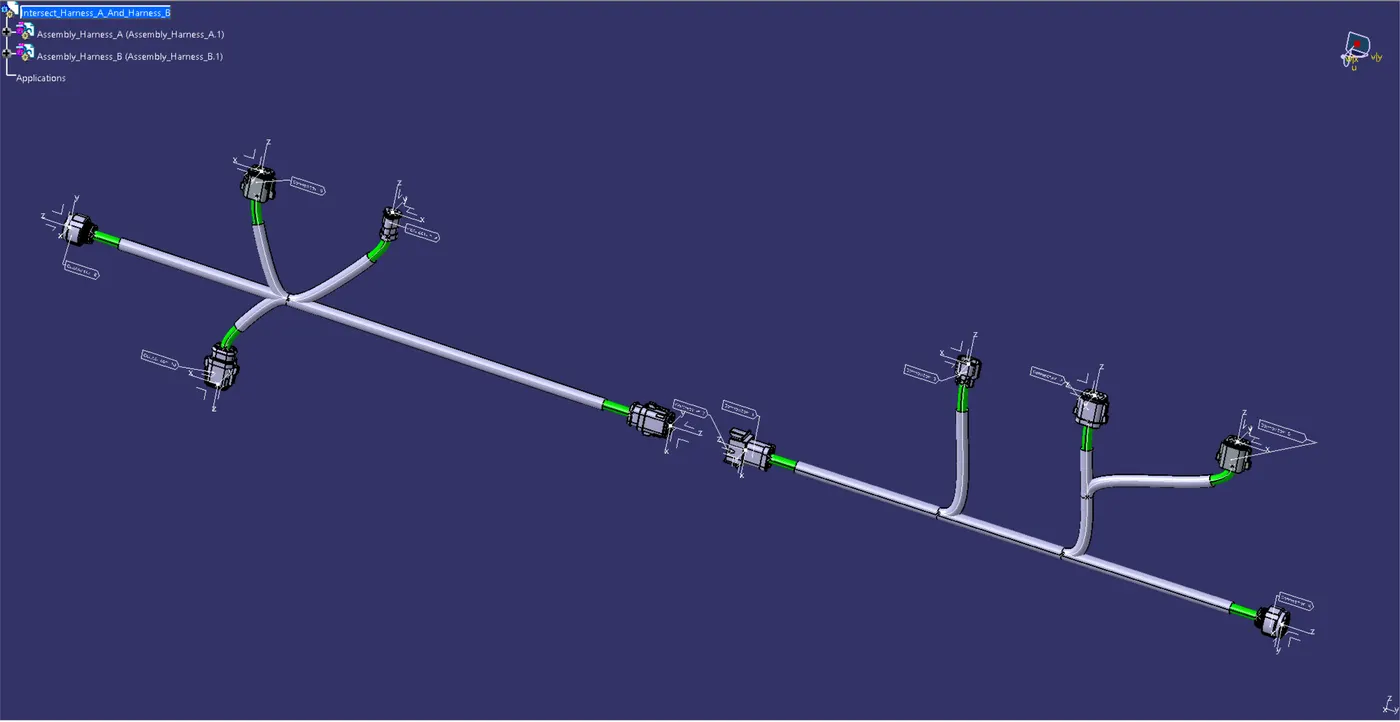
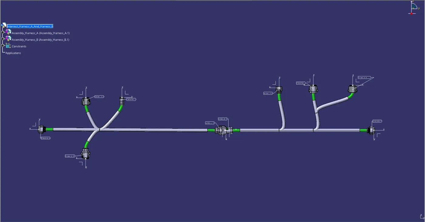
Both Harness A and Harness B need to be connected.
To do so, we must create a new product file with the name Assembly.
Next, call both harnesses in the mechanical assembly design or copy both and paste them into the newly formed product file.
In order to electrically link the two harnesses, we must proceed with Electrical Assembly Design. To accomplish that, choose "connect electrical devices," and an electrical connection will be made between the two harnesses.
It is necessary to insert the male connector into the female connector.
-> IFS FILE CONVERT
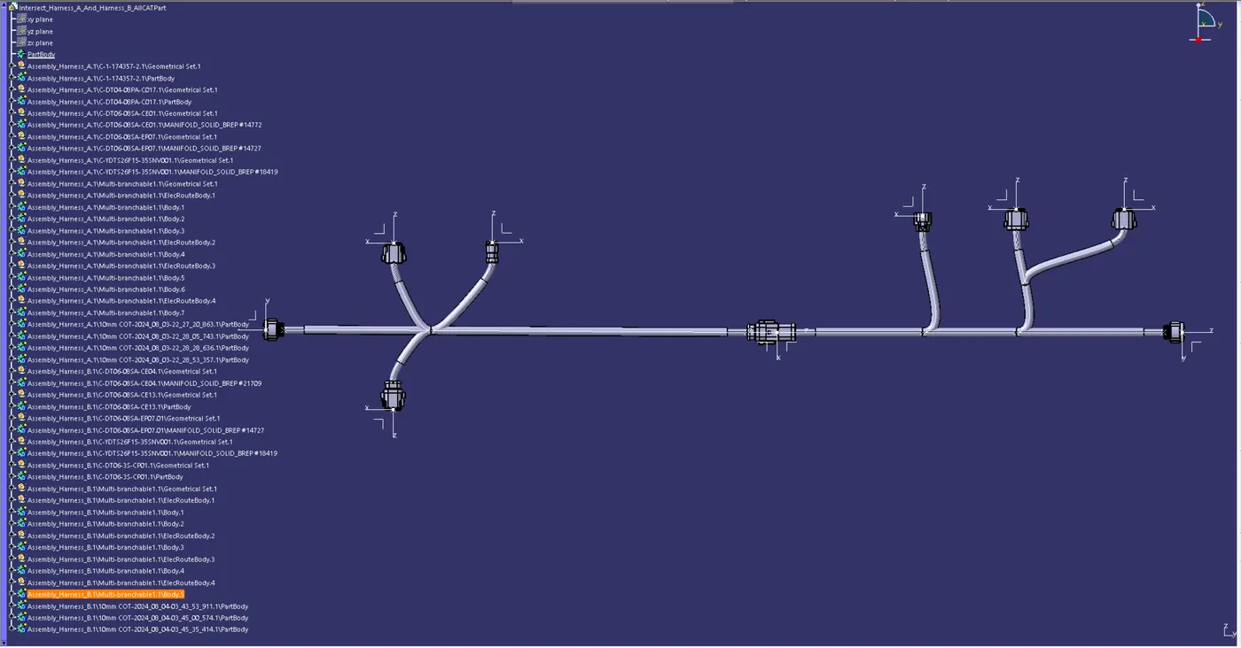
The finished harness assembly file needs to be converted to IGS format. Therefore, the steps listed below must be followed.
Generate CAT Part from product in Mechanical Assembly Design workbench > Tools.
The entire product file is combined into one section after the creation of the CAT portion.
The entire file has now been translated to the IGS format, and the harness assembly is all visible in grey.
Should we need to revert back to the original green hue, we can apply the green color to every bundle segment.
We must use the 'Save as' option in order to save the CAT component file as an IGS file.