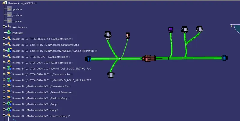
Wiring harness design in CATIA V5 - 3D modeling Week 5 & 6 Challenge
Aim :
To Route the following harness layout in Electrical workbench by makeing assumption for harness bundle diameters and Useing the connectors provided. After completion of routing,
- Check the bundle Continuity. Add snap of result in submission
- Add annotation to all connectors. Make an assumptions for annotations like connect 1 , 2 etc
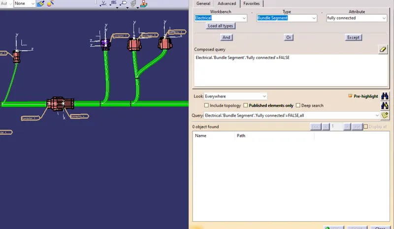
- Check for the bundle warning. Add snap.
- Generate CAT.part of harness assembly and convert is in. igs format.
Creating the Connector Connection point and Bundle Connection point for all the given connectors.
Connector connection point:
- Create midpoint on the contact face which will be normal to wire bunddle insertion.
- Craete Axis System with respect to the point which we have created and defining the axis direction.
- Create Connector connection point.
Bundle connection point:
- Create Bundle connection point.
- Define Bundle connection point.
- After all the connectors are defined, the workbench was switched to Electrical Harness Assembly where Geometrical Bundle was activated.
- All the connectors were routed usingthe Multi-Branchable Document command.
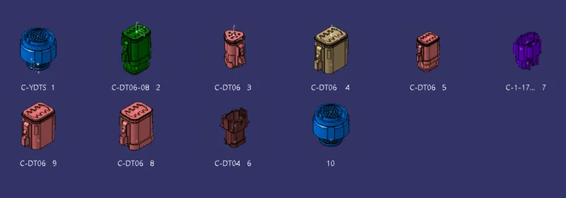
Catalogue creation
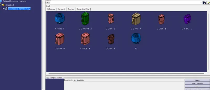
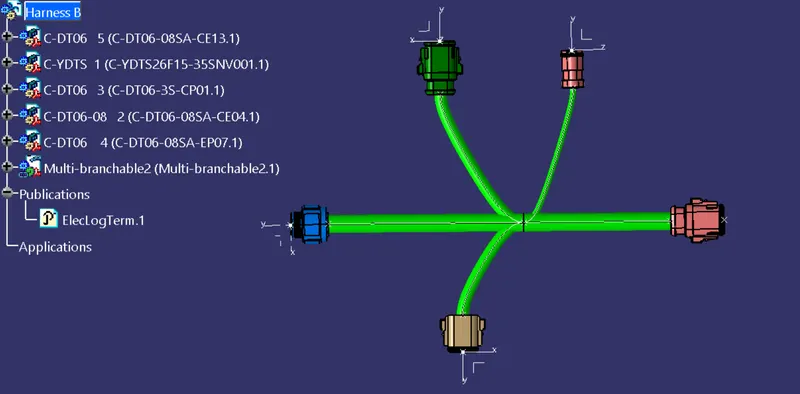
HARNESS B
HARNESS A
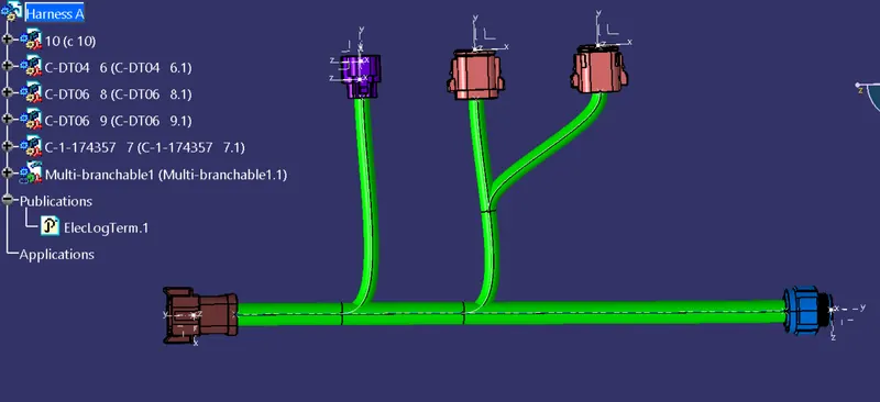
Harness Assembly
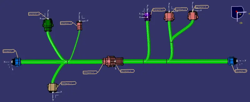
1)Check the bundle Continuity
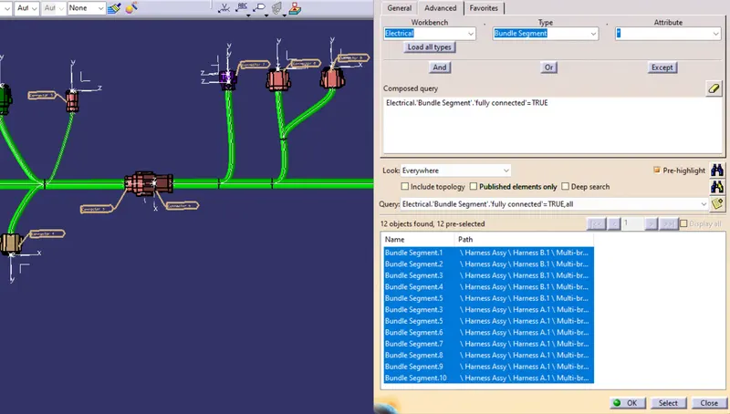
2) Add annotation to all connectors
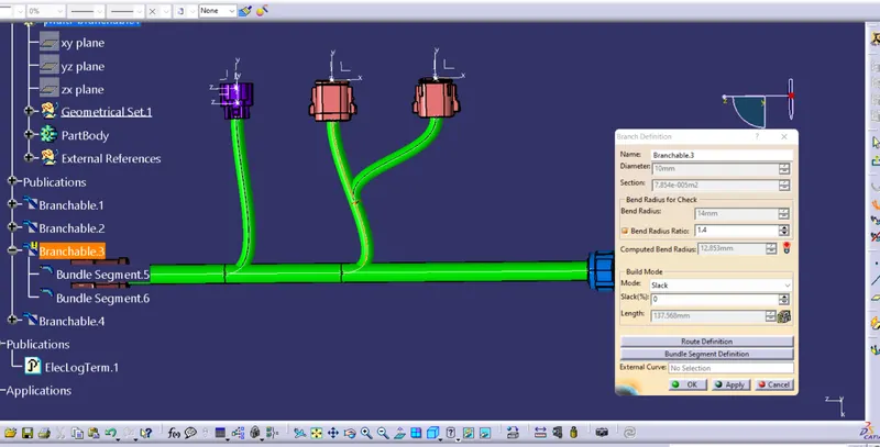
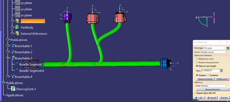
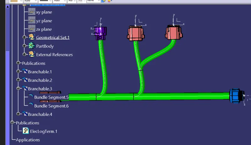
3) Check for the bundle warning.
After checking warning we correct the error by moveing a bundle branch point towards the left. Then it was corrected.
4) Generate CAT.part of harness assembly and convert is in. igs format.