Week 8 - Challenge 6 - Core & Cavity Design
Switch Bezel
Objective
To Create the Core and cavity blocks for the switch bezel and to do Draft analysis for switch bezel.
Tooling axis
The axis in which the mold or core and cavity is opens or the axis which the designer can modify or create a model by taking axis as a reference is called Tooling Axis.
Procedure to creat tooling axis.
- Checking the Class A Surface, for to check which is the perfect place to create a tooling axis.
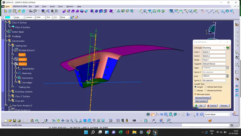
- Insert an axis system to the Class A Surface and by useing multipal extract, extract the base surface of the Class A Surface.
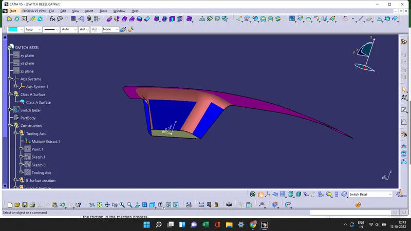
- By selecting base as a reference surface create a point and by selecting the line and click on point-direction option and create a line in Z- Direction.
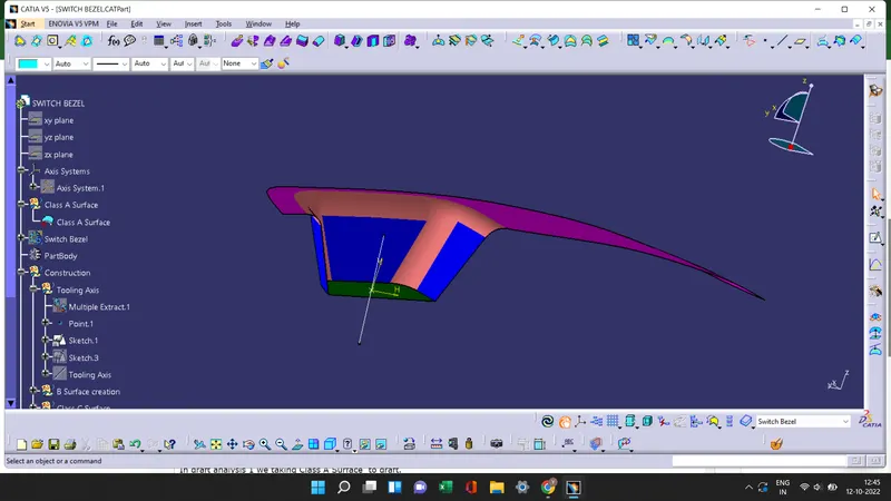
- By taking side wall as a reference create another line from the point in xz direction at an angle of 5 degree.
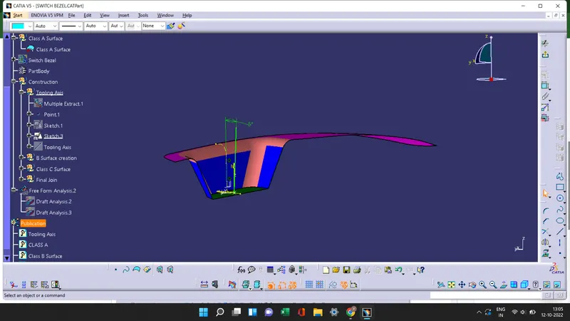
- By Bisecting line 1 and line 2 from sketch 1 and sketch 3 with the point 1 we get the Tooling Axis and publish that tooling axis
Draft analysis
Draft analysis is a method to check the draft angle of the model in various faces and to creates draft on the surface to reduce the friction in the Ejection process.
Procedure to Draft analysis
Draft analysis 1
- In draft analysis 1 we taking Class A Surface to draft.
- Check the view mode and change it to material mode.
- Select the draft analysis tool in the tool bar and select Campass in the Direction option of the draft analysis tool. Then move the campass on the tooling axis at draft direction and lock the draft direction.
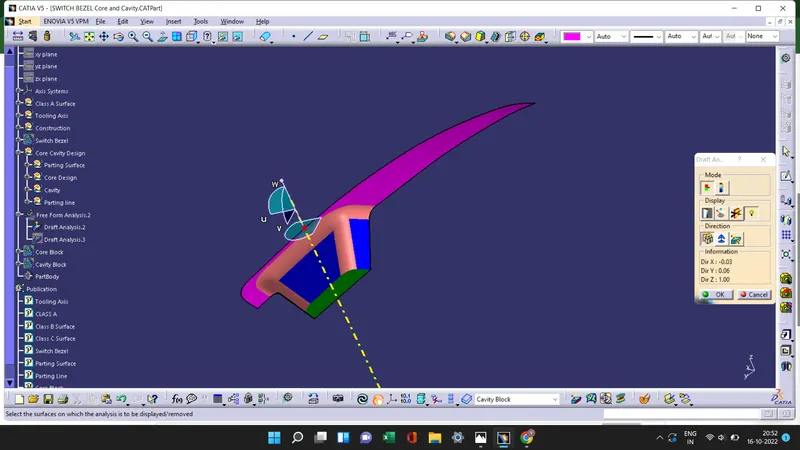
- Useing the running pointer we see the draft angle at different surfaces of the Switch Bezel .
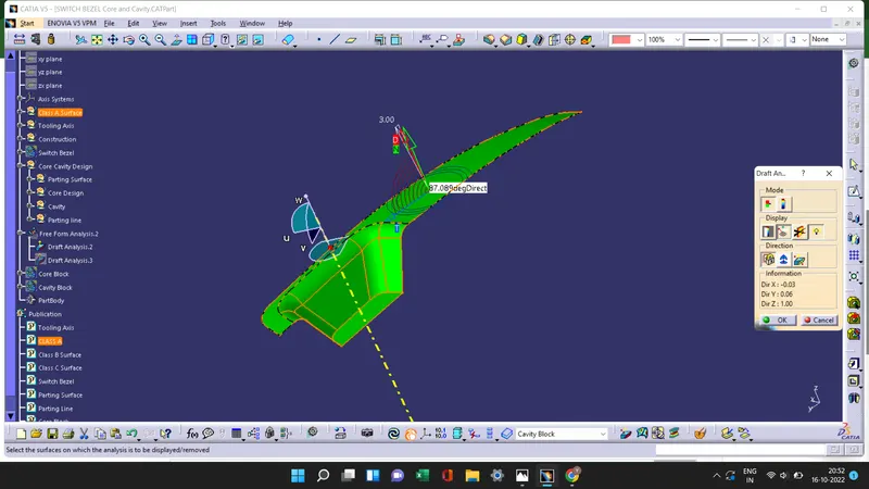
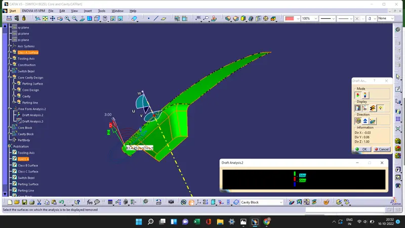
- Then by useing the color scale option we can change the Draft angle.The green color shows if the draft angle is 3 degree,red shows if the draft angle is between 0 to 3 and blue shows the negative draft angle.
Draft analysis 2
- In draft analysis 2 we taking Final Solid surface to draft.
- Select the draft analysis tool in the tool bar and select Campass in the Direction option of the draft analysis tool. Then move the campass on the tooling axis at draft direction and lock the draft direction.
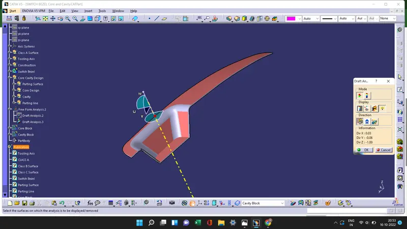
- Useing the running pointer we see the draft angle at B surface and C Surface of the Switch Bezel.
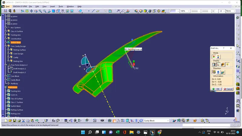
- Then by useing the color scale option we can change the Draft angle.The green color shows if the draft angle is 2.9 degree,red shows if the draft angle is between 0 to 2.9 and blue shows the negative draft angle.
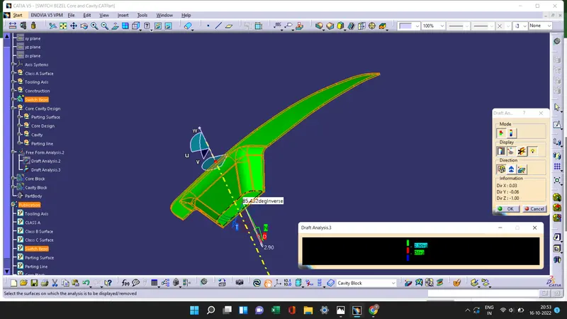
Screenshots of the Draft analysis report for both the given Class-A surface and the final plastic component
Class A Surface
Solid Surface
Screenshots of the core and cavity blocks in various orientations
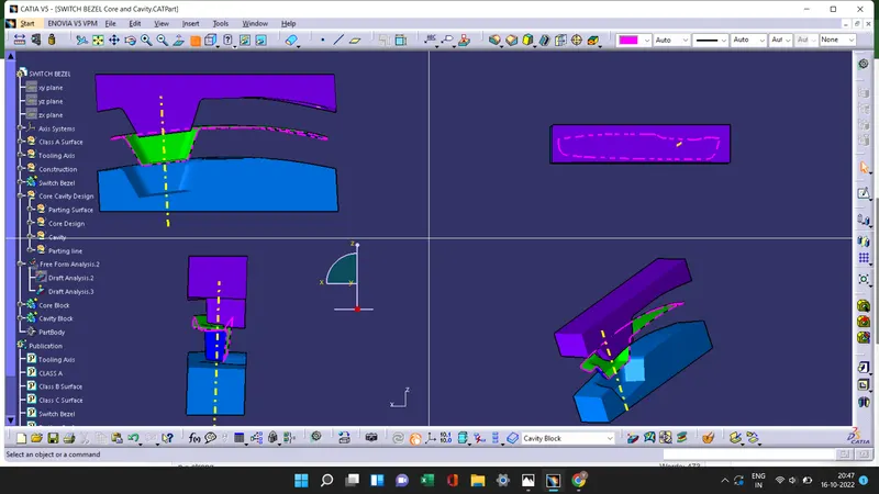
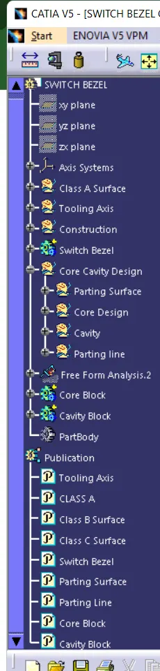
Tree