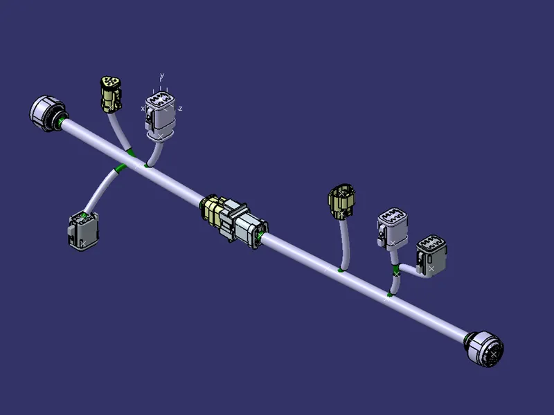
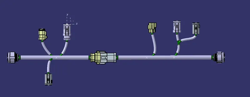
Wiring harness design in CATIA V5 - 3D modeling Week 5 & 6 Challenge
AIM
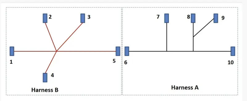
To the given below harness layout we must route. According to the layout to make assumption for harness bundle diameters and use DT connectors.
An electrical connector is an electromechanical device used to join electrical termination and create an electric circuit. Electrical connectors consist of housing, terminals, wedge locks, seals, cavity, mounting cam.
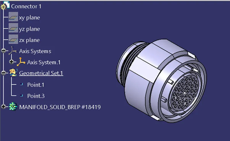
To define all the connectors geometrically and electrically as shown in below images.
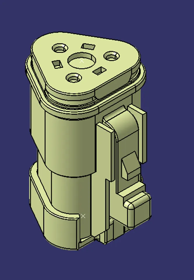
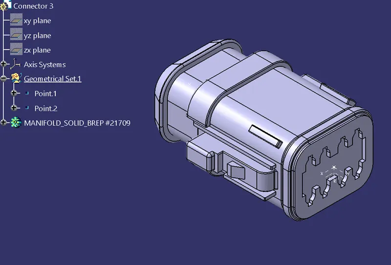
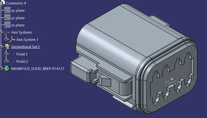
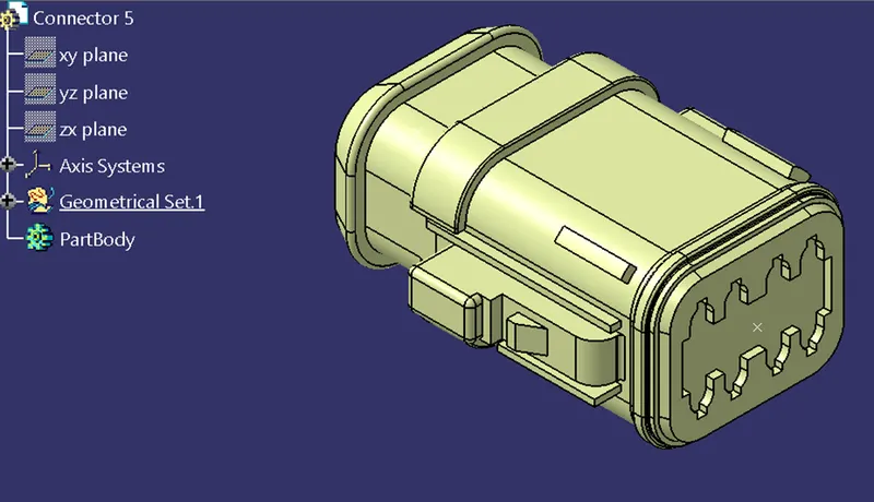
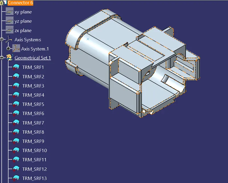
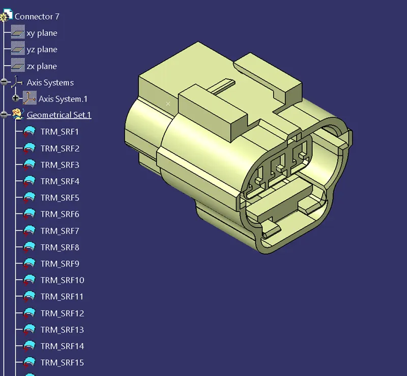
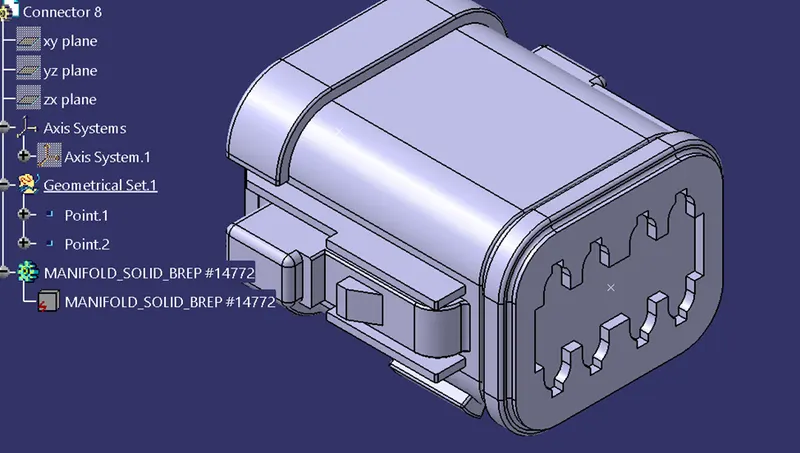
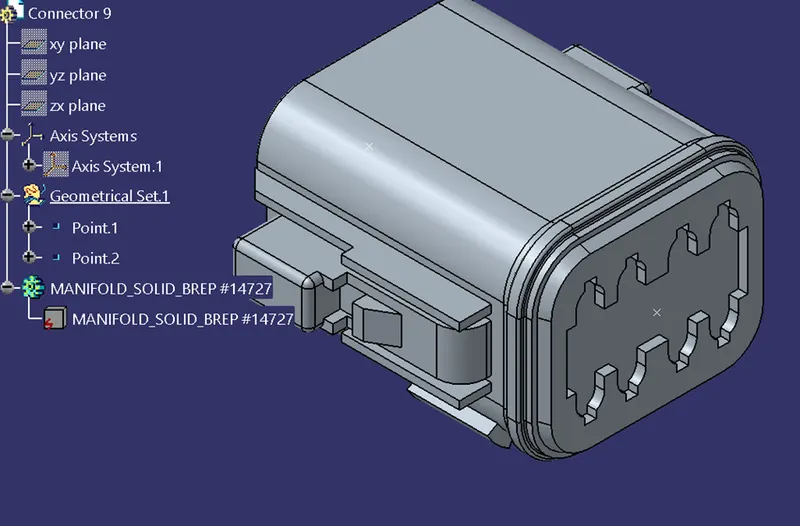
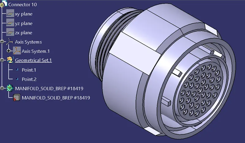
To create Harness A and Harness B by using electrical harness assembly according to the layout.
Harness A Routing
We must check bundle continuity in both Harness A and Harness B in that selecting True option will show all the connected bundle segments while selecting False option will show all the non-connected bundle segments.
Now, we can check for True condition and search for result. All the bundle segments are shown connected. So, there is bundle continuity in both Harness A & Harness B.
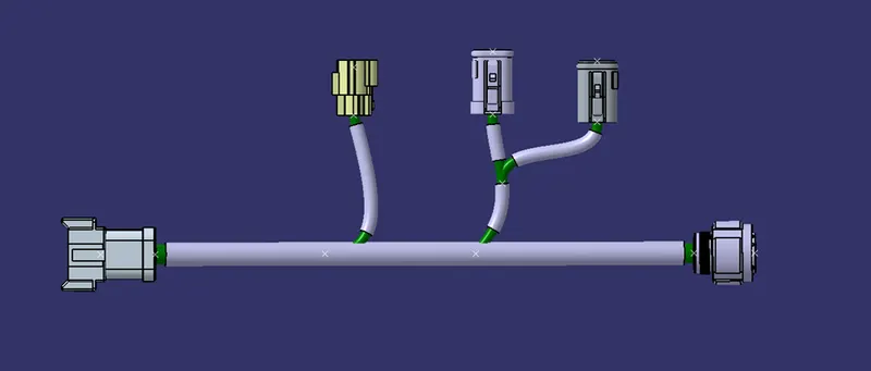
Harness B Routing
After all the connectors are defined, the workbench was switched to Electrical Harness Assembly where Geometrical Bundle was activated. All the connectors were routed using the multi-Branch able Document command.
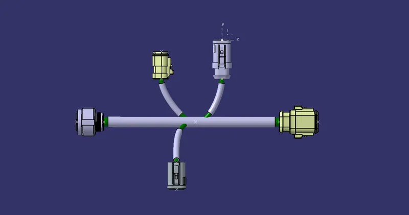
Harness Assembly
We must add annotations for all the connectors in mechanical assembly design workbench. Annotations are used for giving connector names, functions etc.
For this, we must select a plane where annotation will be placed. In the image below, we have selected the front plane.