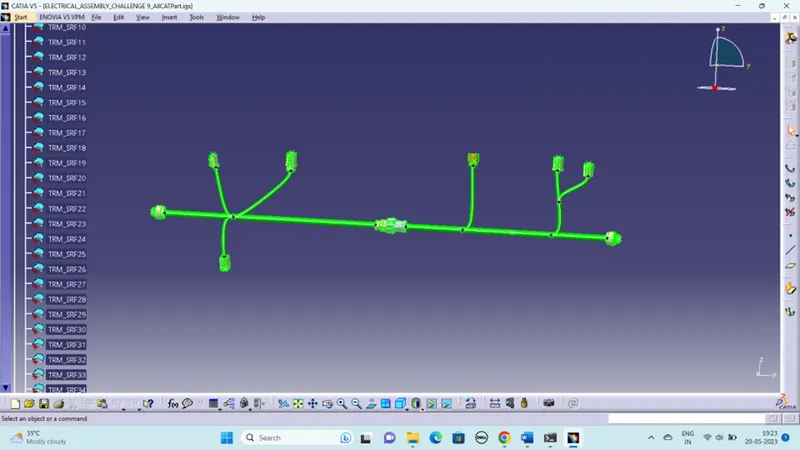
Wiring harness design in CATIA V5 - 3D modeling Week 5 & 6 Challenge
WIRING HARNESS DESIGN IN CATIA V5 - 3D MODELING WEEK 5 & 6 CHALLENGE
AIM:
To Route the following harness layout in Electrical workbench. Make assumption for harness bundle diameters. Use the connectors provided. After completion of routing,
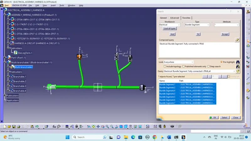
- To Check the bundle Continuity. Add snap of result in submission
- To Add annotation to all connectors. Make an assumptions for annotations like connect 1 , 2 etc
- To Check for the bundle warning. Add snap.
- To Generate CAT.part of harness assembly and convert is in. igs format.
GIVEN CIRCUIT DIAGRAM:
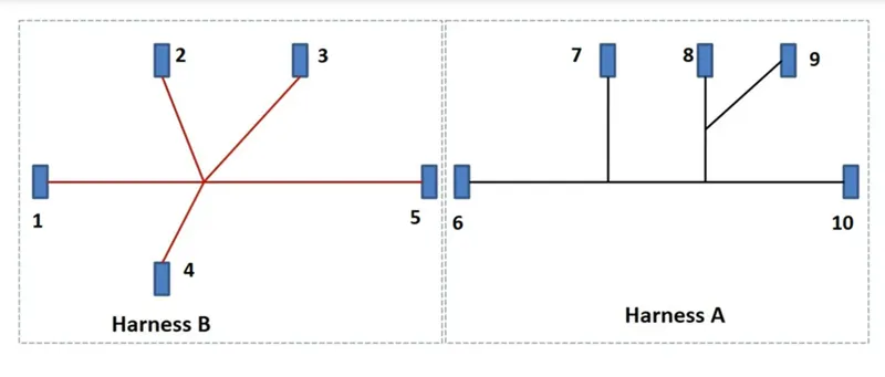
STEPS TO FOLLOW:
- Create midpoint on the contact face which will be normal to wire bundle insertion.
- Create Axis System with respect to the point which we have created and defining the axis direction.
BUNDLE CONNECTION POINT:
- This point is located at center of the bundle segment side or wire entry side. This is the point where bundle segment or wire point end when get routed to a connector. This point is known as Bundle Connection Point.
SWITCH TO 'ELECTRIC PART DESIGN'
- Define the part as connector in CATIA, give no. of termination as 8 because we have 8 entry points for wire.
- Define Bundle connection point.
- Define connector connection point.
ARRANGING THE CONNECTORS BY FOLLOWING THE LAYOUT
- By using the snap and manipulation command arrange the connectors into the desire position.
HARNESS A:
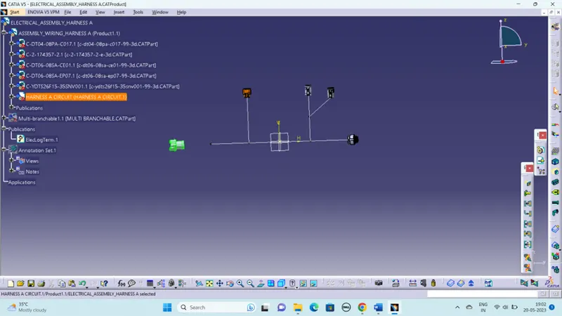
Then create the bundle segment for the given circuit to connect the connectors.
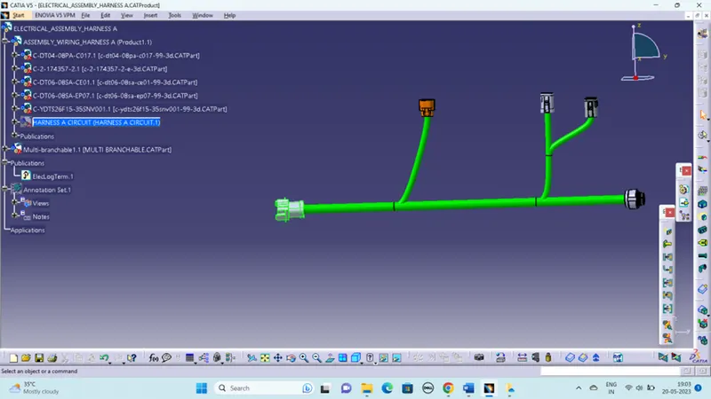
Check the bundle connection,
HARNESS B:
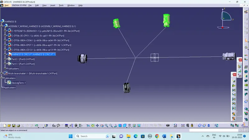
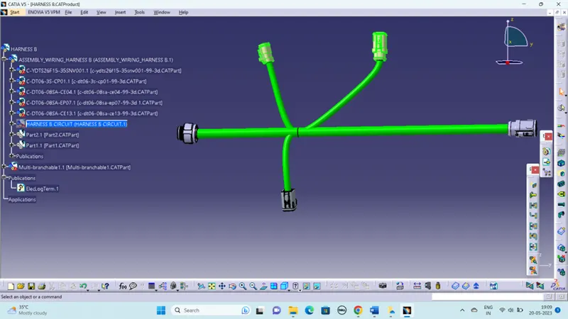
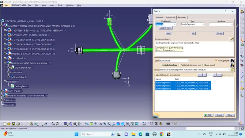
By using wiring harness assembly tools (connect electrical devices) to connect the both circuits.
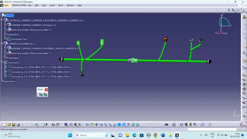
ANNOTATION:
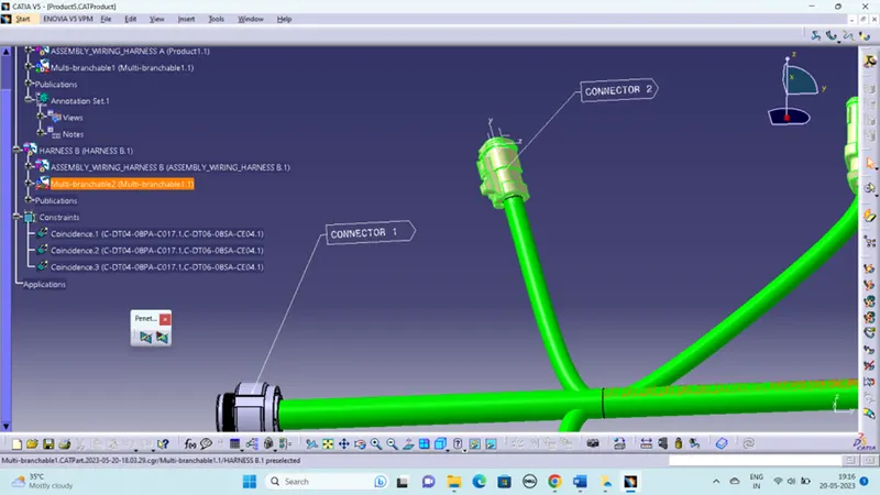
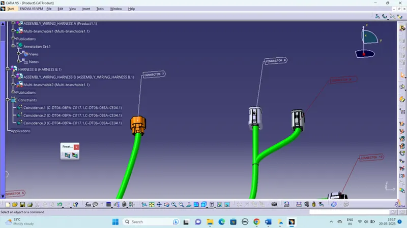
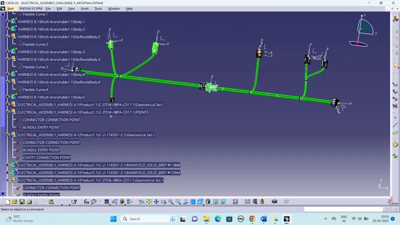
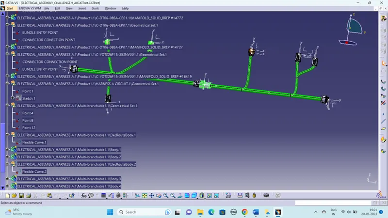
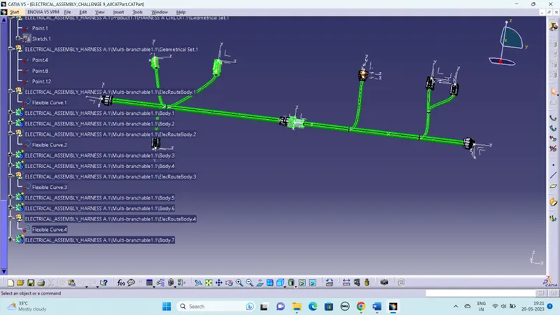
Then convert the product to cat part file and the save as an igs format. The bellow given tree structure shows that,
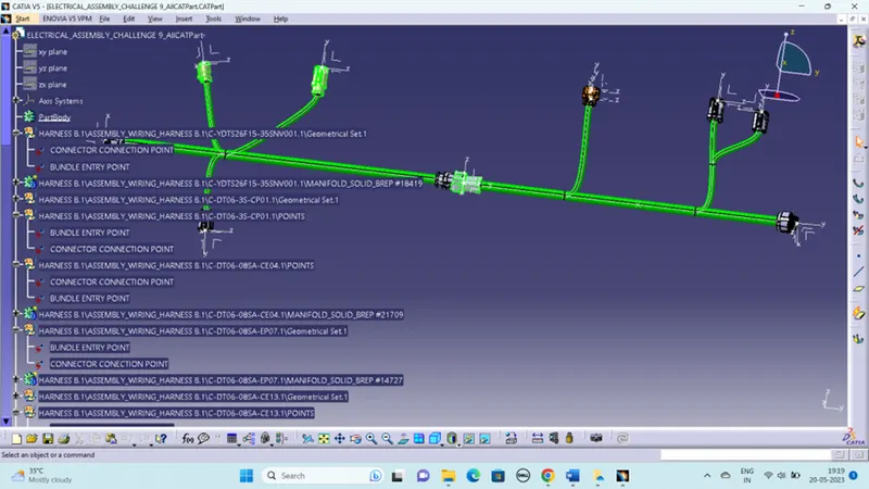
Save as igs file,