Wiring harness design in CATIA V5 - 3D modeling Week 5 & 6 Challenge
Solution
Step 1
For each electrical connector that will be a part of the wiring harness, create the geometric and electrical definitions.
Harness A - Connectors
Connector No. 6
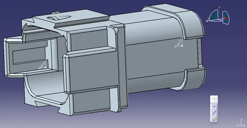
Connector No. 7
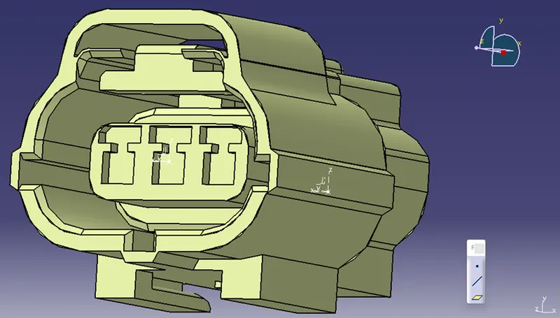
Connector No. 8
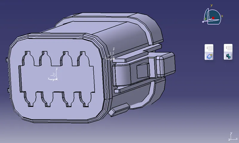
Connector No. 9
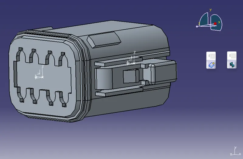
Connector No. 10
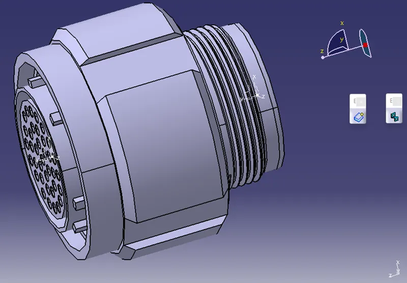
Harness B - Connectors
Connector No. 1
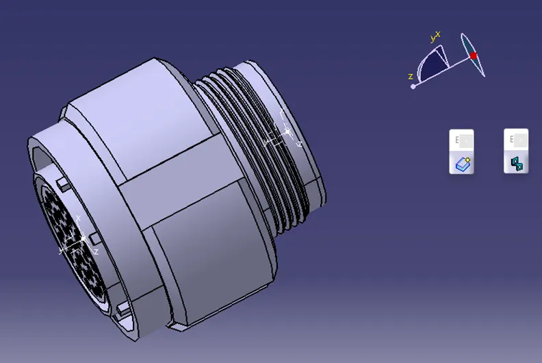
Connector No. 2
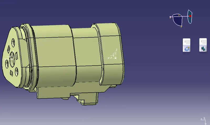
Connector No. 3
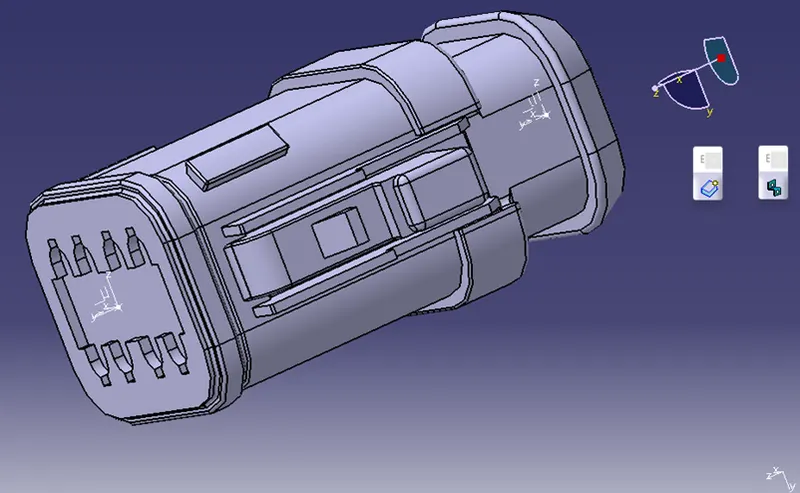
Connector No. 4
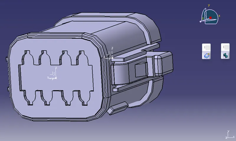
Connector No. 5
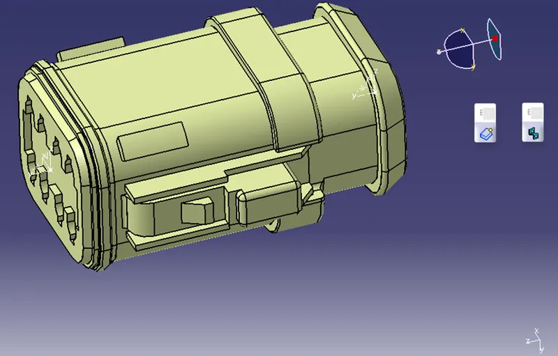
Step 2
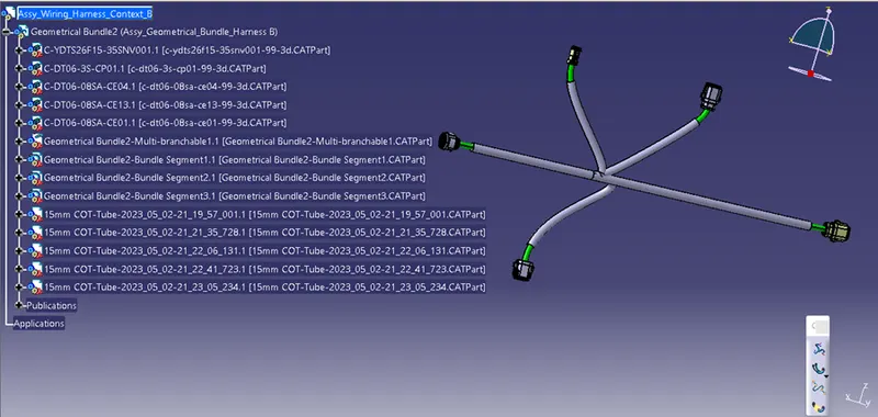
Develop harness A and harness B using the CATIA V5 electrical harness workbench as illustrated below. The connectors are initially all positioned correctly. Then, bundle segments with points for branching and branches are built up between the connectors. For all bundle segments, 10mm bundle diameters are assumed. The bend ratio is set to 1.4 for the entire bundle of segments. For both harnesses, apply the protective coverings, keeping an end extremity of 30mm.
Harness A
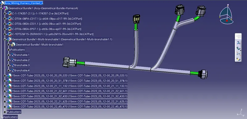
Harness B
Step 3
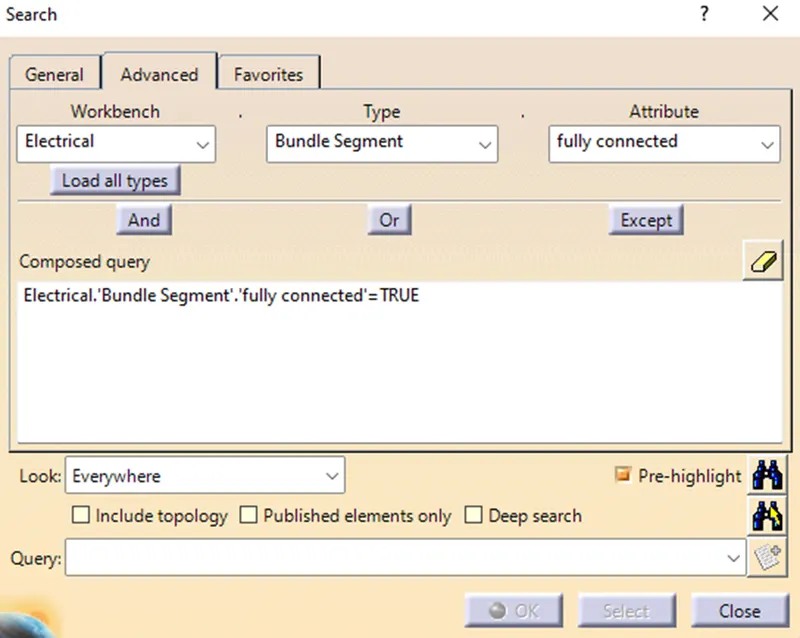
The bundle continuity needs to be examined after harness A and harness B are created. Then, go to Edit>Search>Advanced>Electrical Workbench>Type-Bundle Segment>Attribute-Fully Connected. Make sure multi-branchable is chosen. All connected bundle segments will be displayed if "TRUE" is chosen, but all disconnected bundle segments will be displayed if "FALSE" is chosen.
Step 4
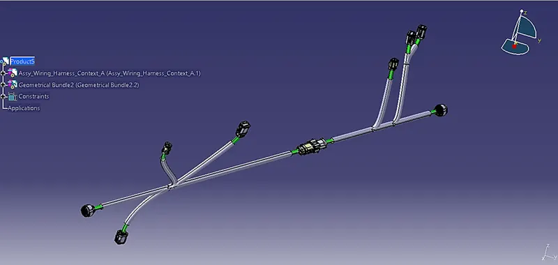
Wiring Harness A and Harness B must be electrically connected in this step. The two harnesses need to be electrically connected, which requires a few procedures. Start by making a new product file in CATIA and renaming it "Assy Wire Harness”. The final harness assembly can then be built by adding harness A and harness B to the newly formed product file. Connect the male and female connectors inside the "Electrical Assembly Design" workbench as illustrated below.
STEP 5
We'll check Harness A and B in this phase to see if there are any bundle warnings. Geometric bundle warnings for the Bend radius, Vector position, and bundle diameter are shown. A yellow flash will appear in the tree structure adjacent to the problematic branchable if these inputs or values are wrong. We can solve the issue (if it exists) by introducing slack or by modifying the vector position for the segment point, depending on the route taken by the bundle segment.
STEP 6
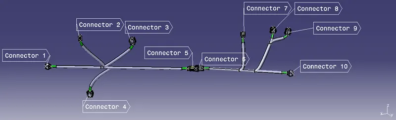
We will label each electrical connector in this phase. Annotations are used to show extra information as well as connect functionalities. They are described in the "Assembly Design" Workbench of CATIA V5. Prior to placing the annotation, we must choose a front plane, then place the annotation at the desired location (for all the connectors). Here, the annotations are placed as given in the question context.
STEP 7
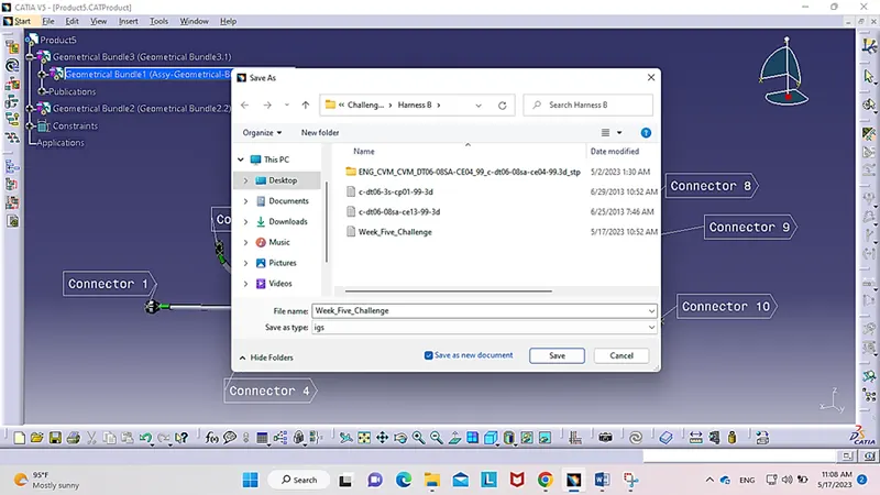
Save the file in “igs” format by clicking on File, then Save as, then specifying the file type as “igs”, and make sure to tick “Save as new document”. Also, it is possible to name the file, as desired.