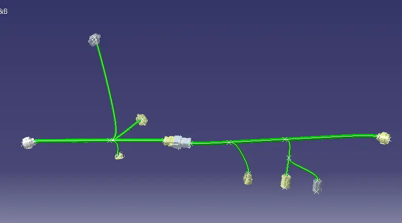
Wiring harness design in CATIA V5 - 3D modeling Week 5 & 6 Challenge
Aim :-
- Route two electrical harnesses per the given layout and interconnect them as a single harness assembly
- check for bundle continuity, and bundle warnings, and then provide annotations for the final harness assembly.
Procedure :-Step 1 - Download all connectors from given link,
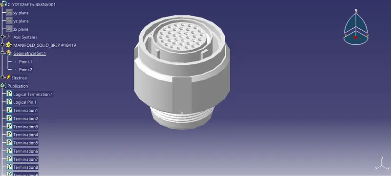
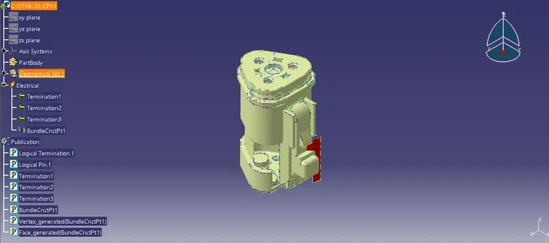
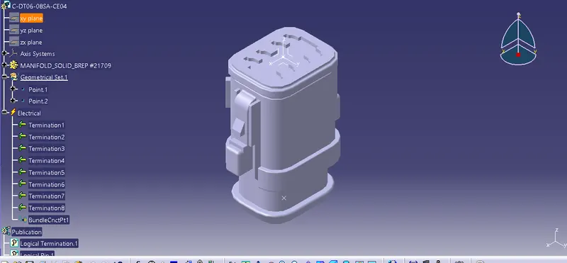
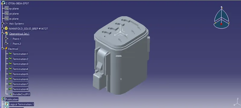
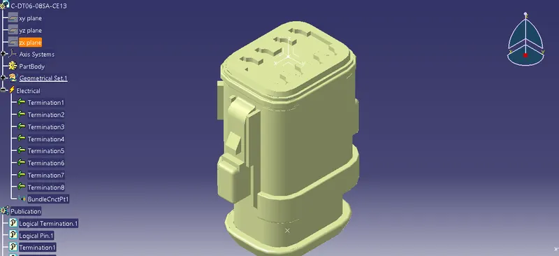
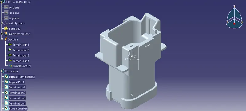
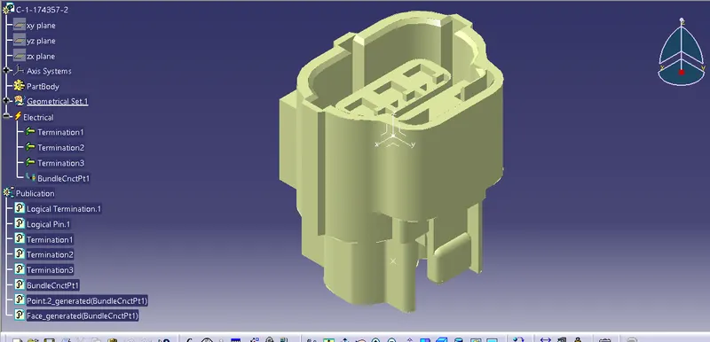
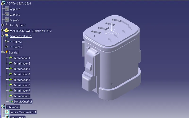
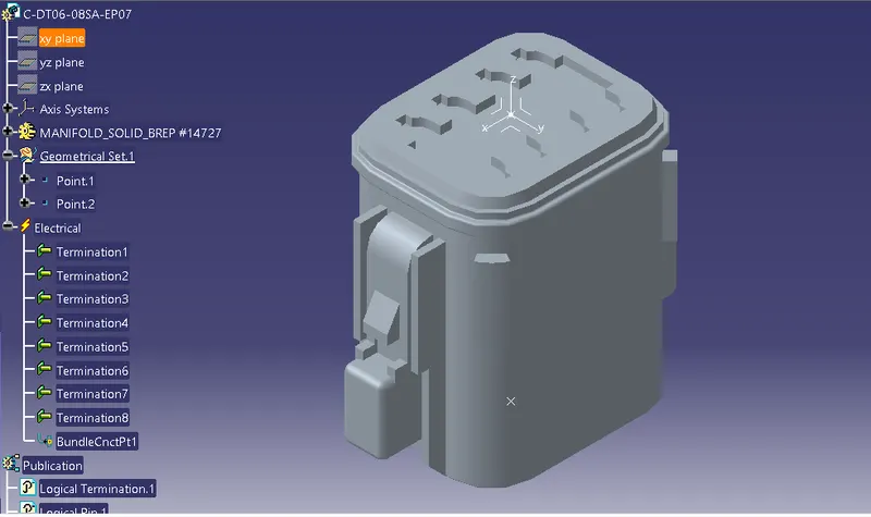
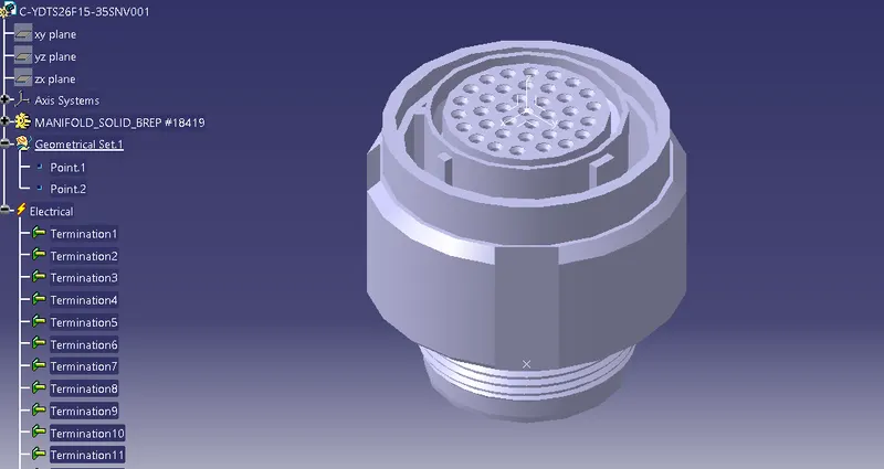
Step 2 - All connectors define electrically and giometrically. so can tyey are used in wiring harness assembly.
1.
2.
3.
4.
5.
6.
7.
8.
9.
10.
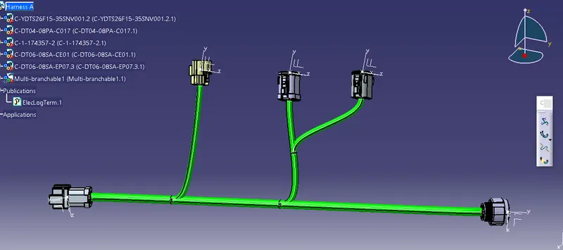
HARNESS A
After all the connectors are defined, the workbench was switched to Electrical Harness Assembly where Geometrical Bundle was activated. All the connectors were routed using the Multi-Branchable Document command.
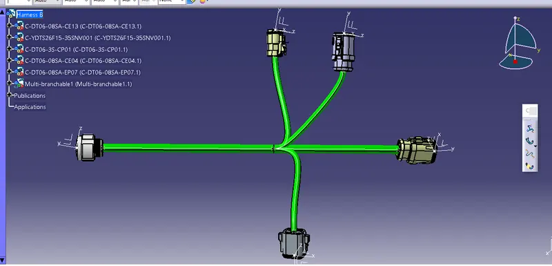
HARNESS B
After all the connectors are defined, the workbench was switched to Electrical Harness Assembly where Geometrical Bundle was activated. All the connectors were routed using the Multi-Branchable Document command.
STEP3- After Harness A and Harness B are created the next step is to check the bundle continuity.
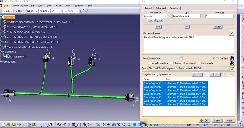
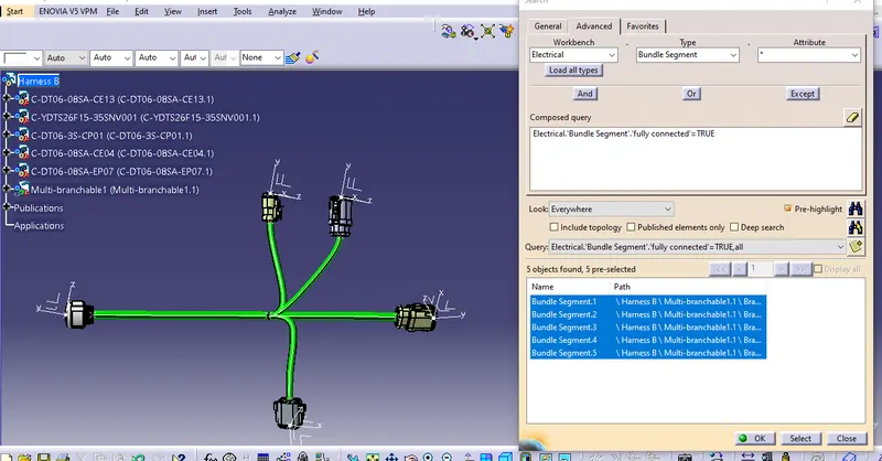
Selecting the "TRUE" option will show all the connected bundle segments while selecting the "FALSE" option will show all the non-connected bundle-segments.
For now, we will select the "TRUE" option and search for results. All the bundle segments in Harness A and Harness B will be displayed showing that there is bundle continuity in Harness A and Harness B.
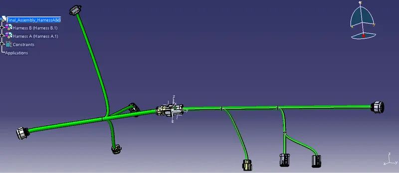
STEP4- In this step, we have to interconnect the Wiring Harness A and Harness B electrically. There are a few steps that have to be followed to connect the two harnesses electrically.
First, make a new product file in CATIA and rename it as "FINAL HARNESS ASSEMBLY". Make sure to open the three windows vertically as shown below.
STEP6- In this step, we will be adding annotations for all the electrical connectors.
Annotations are used to show connector functions and additional information. They are defined in Assembly Design Workbench of CATIA V5.
First, we have to choose a plane on which the annotation will be placed. Here we will be choosing the front plane as shown below for Harness A. We should make sure that the geometrical bundle is active before choosing the annotation plane.
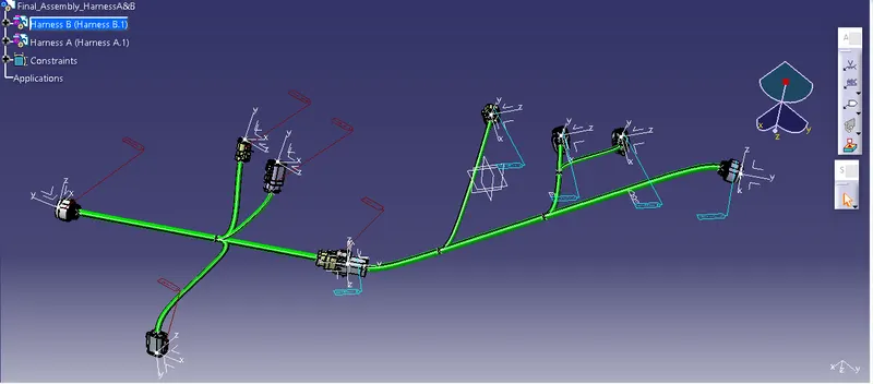
*convert final Assembly in igs file*