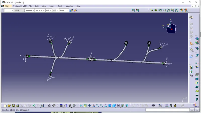
Wiring harness design in CATIA V5 - 3D modeling Week 5 & 6 Challenge
Aim:
- Route two electrical harnesses per the given layout and interconnect them as a single harness assembly
- check for bundle continuity, and bundle warnings, and then provide annotations for the final harness assembly.
Objective:
- The objective of this project is to first route the two Harness A and Harness B as per the given harness layout.
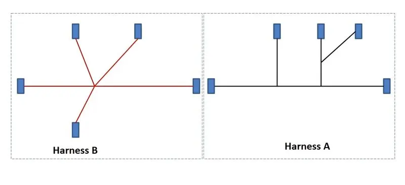
Figure 1: Shows the layout of two Harness A and Harness B
The electrical connectors are represented by numbers in the above figure. There are 8 different types of connectors at 10 different locations.
2. Bundle continuity has to be checked for the two created harnesses.
3. After the two Harnesses are created, the next objective is to have them interconnected electrically.
4. Check for bundle warnings in Harness A and Harness B.
5. Add annotations to all the connectors in Harness A and Harness B.
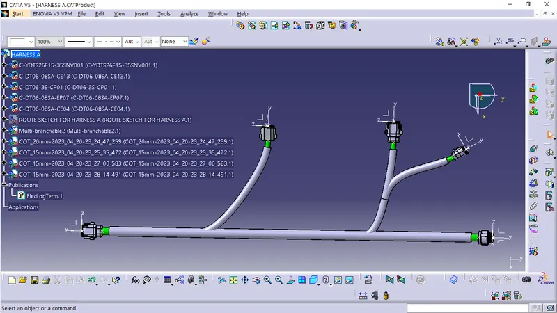
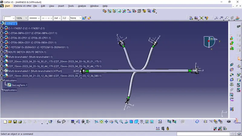
First, we will locate all the connectors at their desired position, add branch points required and create bundle segment according to the diameters assumed as 15mm and 10mm.
Harness A:
Harness B:
Step 3:
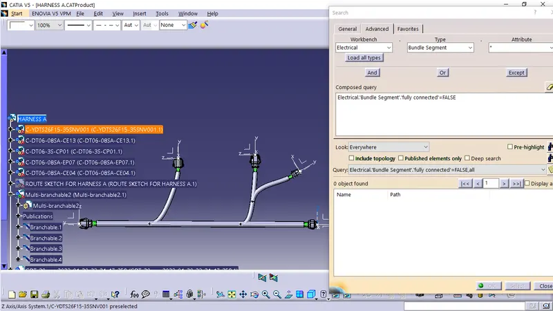
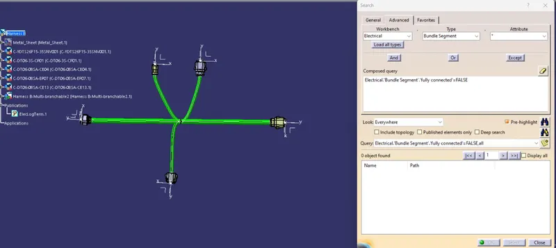
- Now in this step, we must check bundle continuity in both Harness A and Harness B.
- So, for that, go in Edit>Search>Workbench-Electrical>Type-Bundle segment>Attribute-fully connected.
- We will get one window, in that selecting True option will show all the connected bundle segments while selecting False option will show all the non-connected bundle segments.
- Now, we will check for True condition and search for result.
- All the bundle segments are shown connected. So, there is bundle continuity in both Harness A & Harness B as shown in below images.
Harness A:
Harness B:
Step 4:
- In this step, we must interconnect both Harness A & Harness B.
- For that, we must create a new product file and can give the name as Assembly.
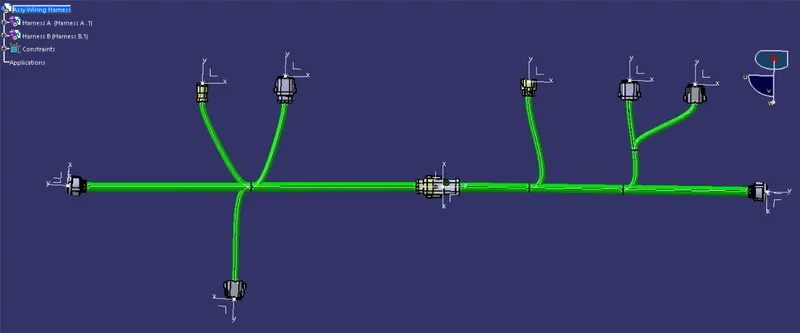
- Then, copy both harnesses and paste it in newly created product file or call both harnesses in mechanical assembly design as below image.
- We must go in Electrical Assembly Design to connect both the harnesses electrically. So, for that, select the option 'connect electrical devices' and both the harnesses will get connected electrically as below.
Step 5:
- In this step, we will be checking the bundle warning in Harness A & B.
- Geometrical bundle warnings are shown for bend radius, bundle diameter and vector position.
- So, if there is any incorrect value or input regarding these factors then yellow colored flash will be appear in the model tree structure next to the branchable with problems.
Step 6:
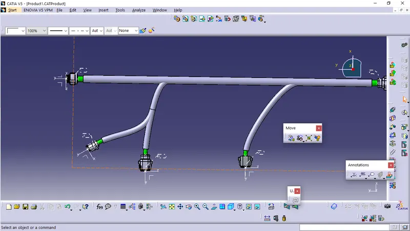
- In this step, we must add annotations for all the connectors in mechanical assembly design workbench.
- Annotations are used for giving connector names, functions etc.
- For this, we must select a plane where annotation will be placed. In the image below, we have selected the front plane.
Step 7:
- Now, in this step we must convert the final harness assembly file into IGS format. So, for that we need to follow the steps below.
- Mechanical Assembly Design workbench>Tools>Generate CAT Part from product.
- Once the CAT part is created, the whole product file is converted into a single part.
- Now, the whole file is converted into the IGS format, and we can see all the harness assembly is looking in grey color.
- If we need to change color as before in green, we can go back and give green color to each bundle segment.