Wiring harness design in CATIA V5 - 3D modeling Week 5 & 6 Challenge
- ELECTRICALLY DEFINITION :
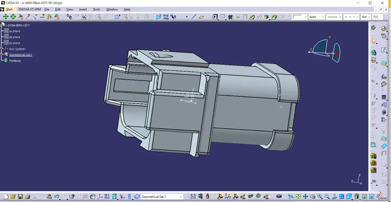
First we will deifned electrical geometry of the connectors whichi is Connector connection poin , connector connection axis system, caonnector Bundle point as shown in the below figure.
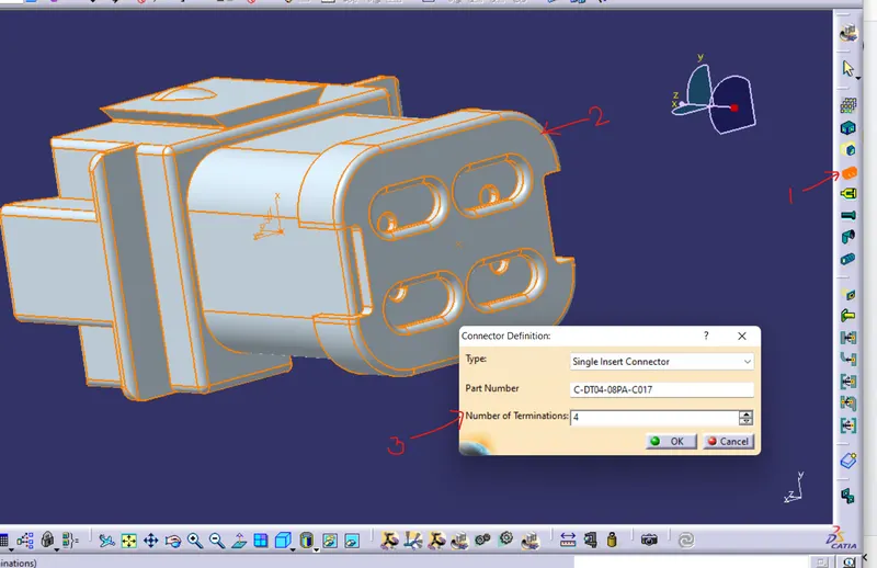
Now we willswitch to Electrical part design workbench and defined the connector ekectrically click on DEFINED COONECTOR>click on part>give no. of bundle entry hole in the connector>ok as shown in below image
Now Go to CONNECTOR CONNECTION POINT>click on part >a popup window will bw open give the neccesary requirements as shown in below image

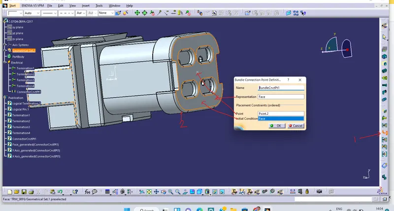
Now we will defined bundle entry poin Go to DEFINED BUNDLE CONNECTION POINT>click on part>a popup window will bw open give the neccesary requirements as shown in below image.
Here our connector are fully defind electrically see below image
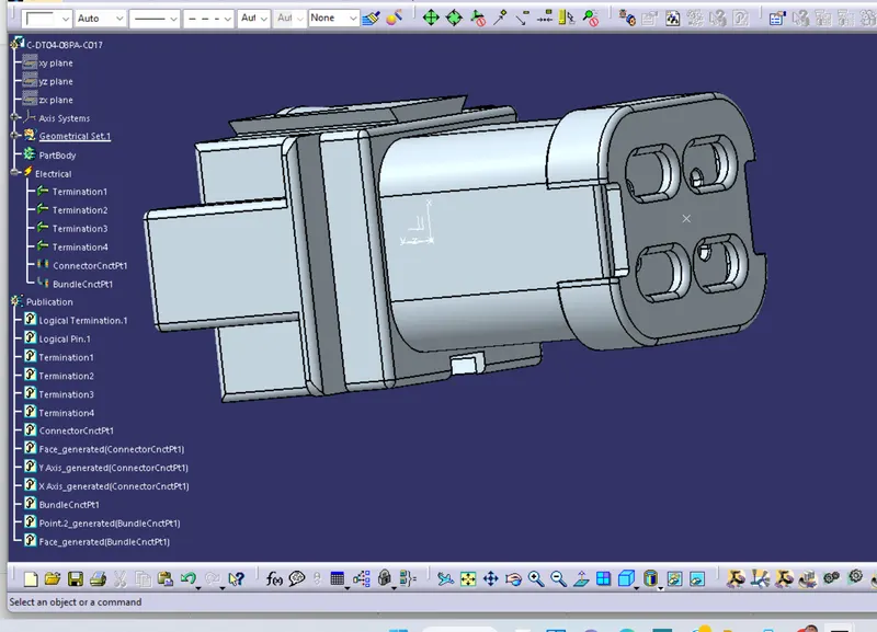
Similarly we will be defning all the connector Electrically so that we can use it latter for bundle routing
Now its time to add these all electrically defined connector in Catalog, For this Go to ELECTRICLA DEVICE>a popup window will bw open give the neccesary requirements as shown in below image, > go to file and select the catalog file where we want to add this connector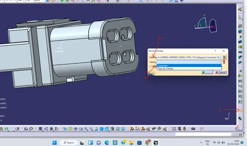
As our all the connectors are added in catalog, go to file>new>product>ok this is our context model geometry, now under this we will add another product file and named it Harness_A, For this right click on context file >component>new product (as shown in below image1). Add all the coonctors from catalog to the Hrness A product file go to CATALOG BROWSER> dOUBLE click on the part whicjh you want to add>ok>close (see below image2)
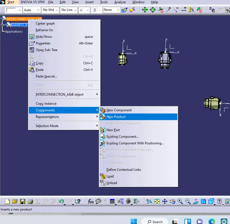
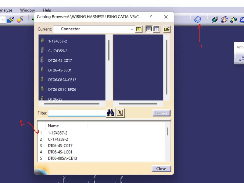
1 2
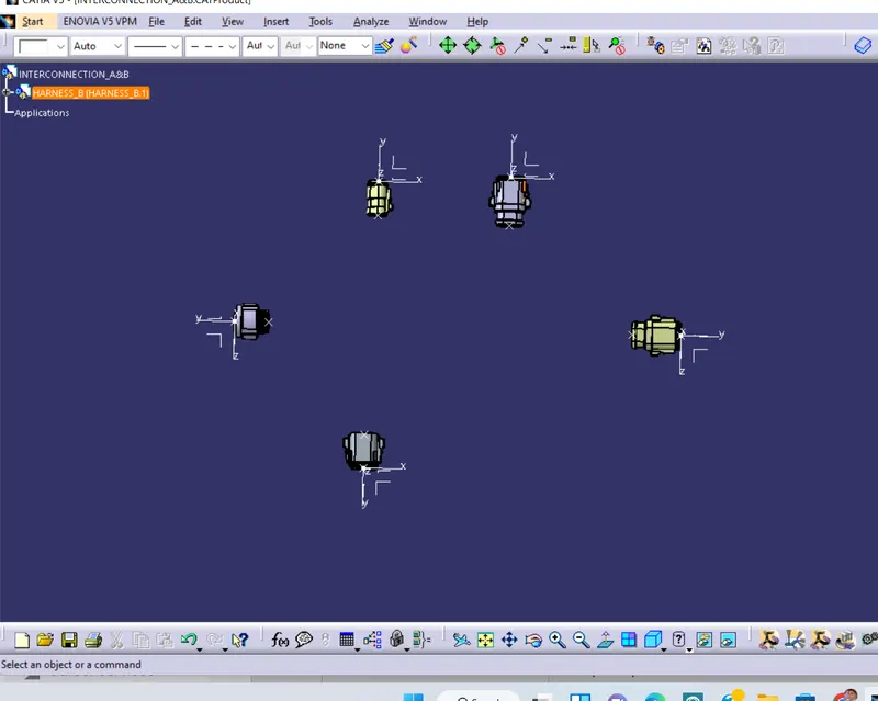
We will switch to Mechanical assambly design> here under the MOVE we have various command available to arrange all the connectors in its desired location like MANIPULATION, SNAP etc. with the help of this move command we can arrange the connectors as we have said to arrange the final arranged connectors shown in below image1
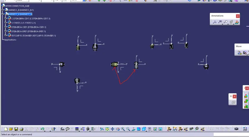
1 2
Now similarly we will create another product file and for Harness_B And add all the necessary parts to it and arrange with the help of move command and save in the same location. see above image 2
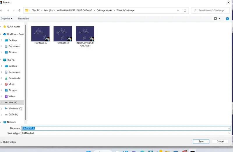
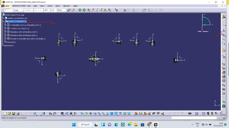
Now we will Switch to electrical Harness Assambly AND defined the the Harness A and B electrically go to GEOMETRIAL BUNDLE > click on the tree harness a now sign will be changed see below image
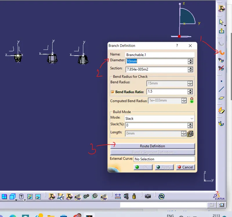
Now go to BRANCH DEFINITION>a popup window will be open give the neccesary requirements as shown in below image1> Route Definition>a popup window will be open again see image2 >Click on the coonectors between which we want to create bundle >ok
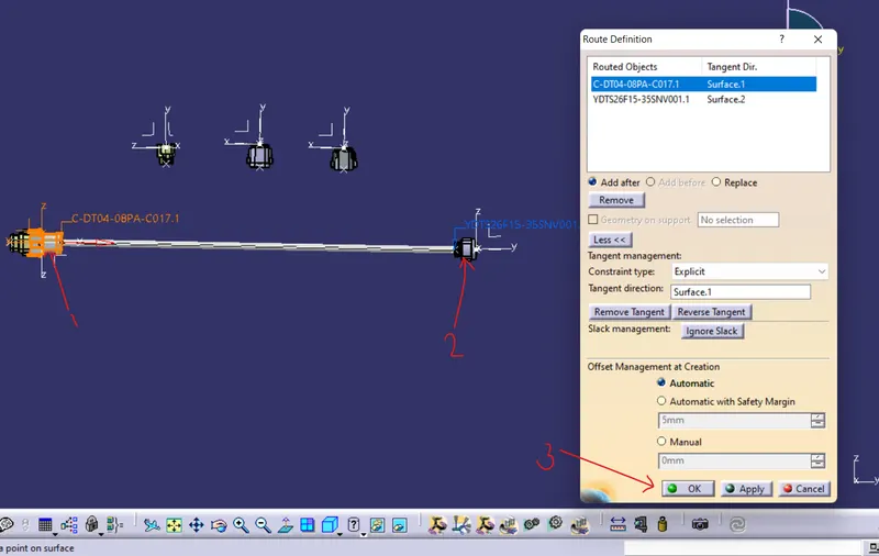
1 2
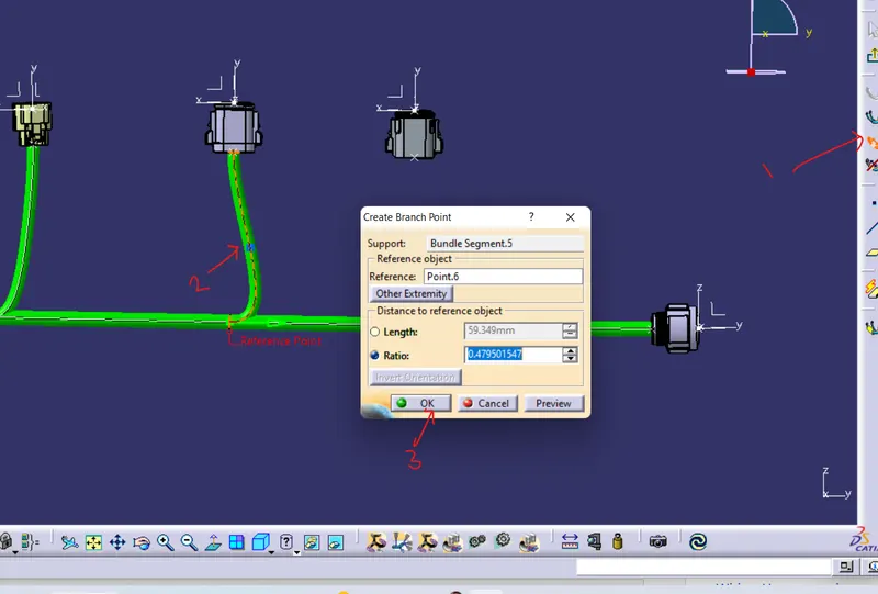
Now go to CREATE BRANCH POINT>click on the budle location from where you want to split the bundle and create branch see below image 1. Now again go to the the BRANCH DEFINITION> This time the bundle diameter should be less than the main trunk bundle diameter image2a>ok >select the bundle and connector as shown in below image2b
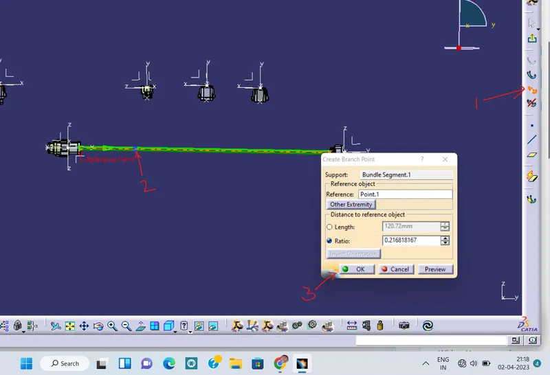
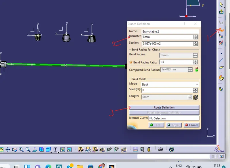
1 2 a
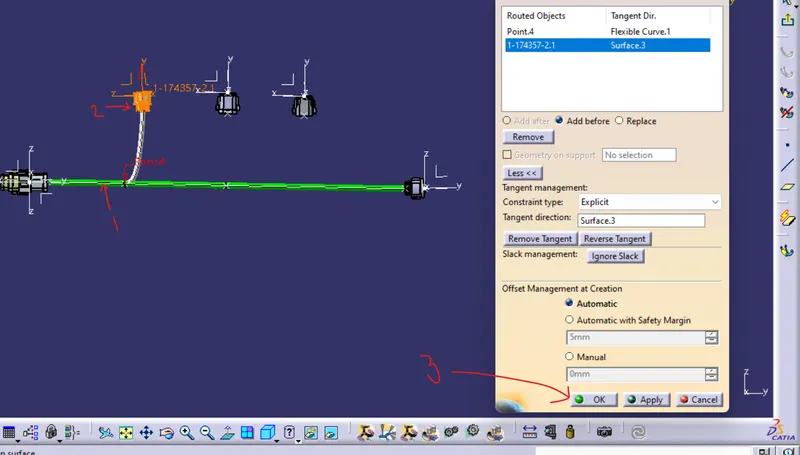
2 b
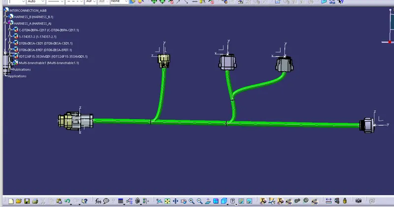
Now agian we will create the a branch point and a sub branch as shown in below image 1 final connector with bundle shown in below image 2
1 2
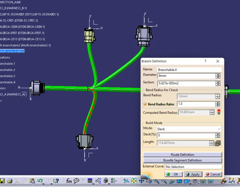
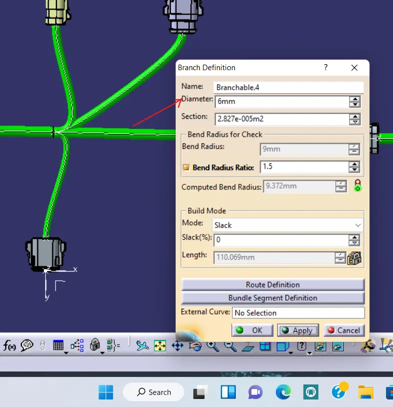
While creating Harness for A we got a BUNDLE WARNING, this warning bacause of the Computed bend radius is less than the bend radius see below image1, Always make sure that the computed bend radius should be greater than the bend radius shown. We have resolved this warning by just decreasing the diameter of the bundle.
1 2
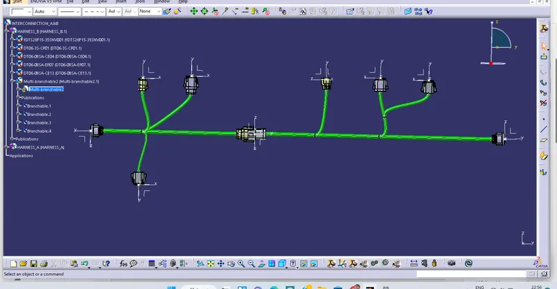
Finally we have got the Wiring harness
- BUNDLE CONTINUITY:
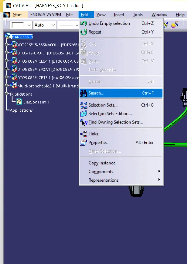
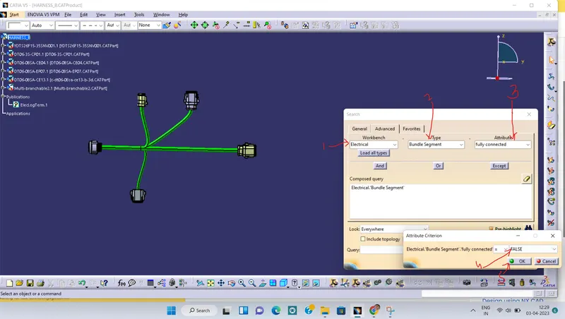
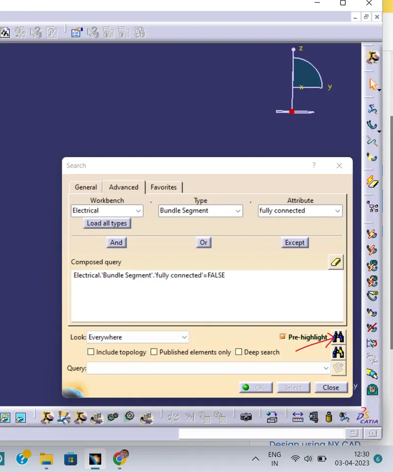
First Activate the Multiple Brancheable>Edit>Search>Advanced>Workbench-Electrical>Type-Bundle segment>Attribute-fully connected>False(to see which bundle is not connected) or True(to see which bundle is connected)>ok > Search here it will show which bundle is coonected or not connected see below images:
1 2
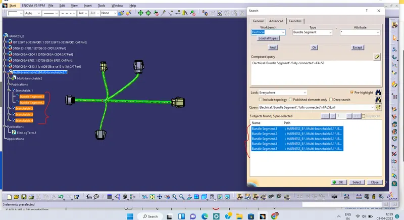
3 4
in above image 4 the highlighted branch is not connected so it is required to delete and re-create the bundle again then again check the coninuity
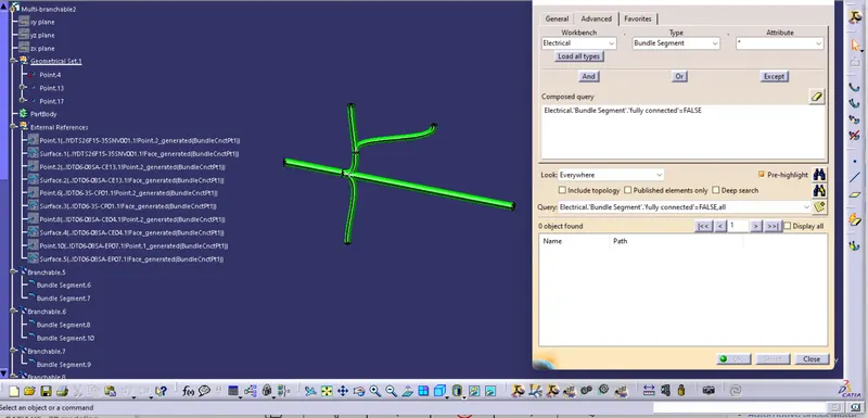
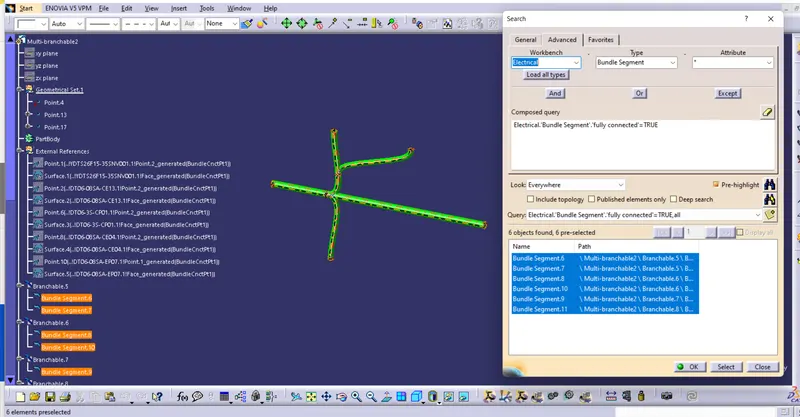
1 2
aftre re created the bundle it is fully connected as shown in image 1 false case and image 2 True case
Similarly we will do the same for the Harness_A
- Annotations:
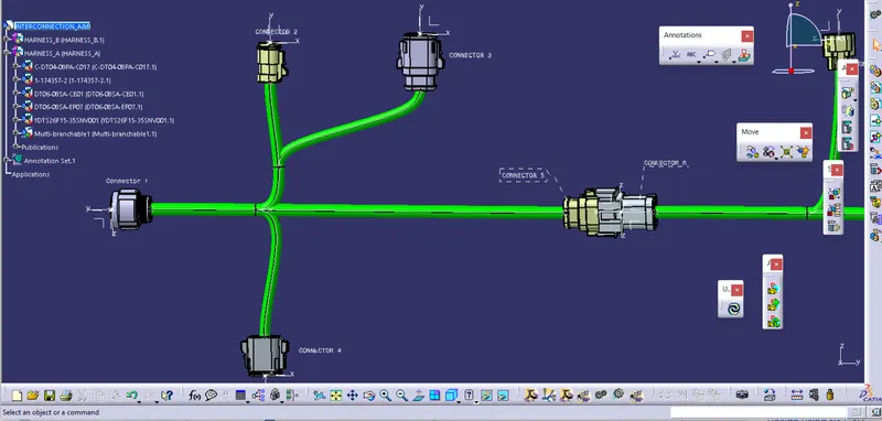
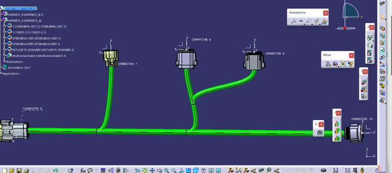
For annotation we will switch to assambly design and Undre Annotation we have TEXT WITH LADEAR, FLAG NOTE WITH LEADER these command is used as ANNOTATION of the conectors see below images
- Creation of CAT.Part:
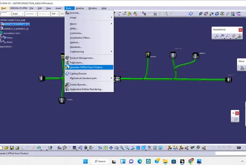
Switch to assambly design >tools>Generate cat part from product >givr name>ok see below image1 > now save this file
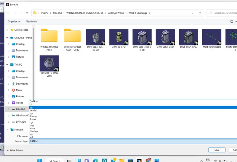
Now for converting into igs go to save as and click o igs>save image2
1 2