Wiring harness design in CATIA V5 - 3D modeling Week 5 & 6 Challenge
Harness A and Harness B Electric Connection
Aim: To create an electric connection between two Electric Harness A and B.
We had already seen how to give Electric properties to the connector in Electric Part Design. After giving an Electric Properties we have to create Geometric Bundle for Electric Harnes A and B.
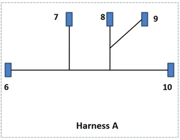
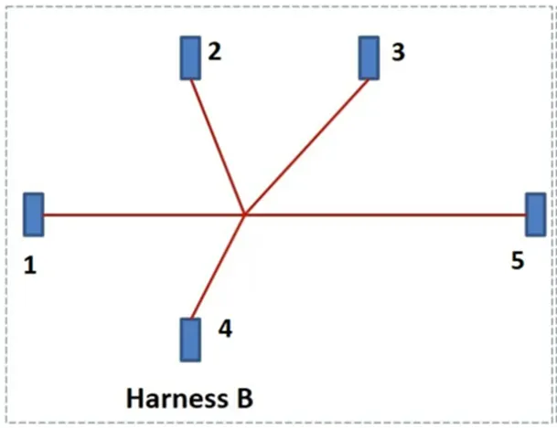
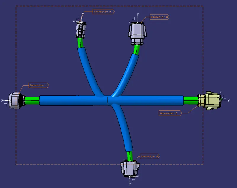
Harness A Connectors: Harness B Connectors:
Connector 6 Connector 5
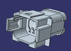
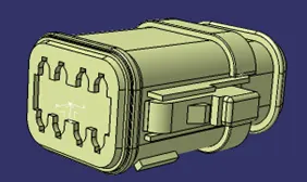
Connector 7 Connector 4
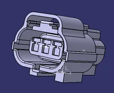
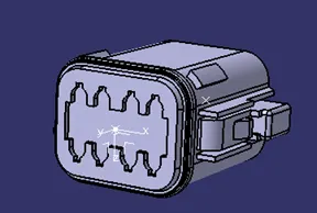
Connector 8 Connector 3
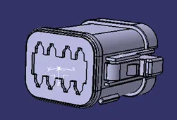
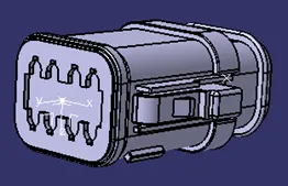
Connector 9 Connector 2
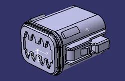
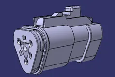
Connector 10 and 1
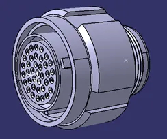
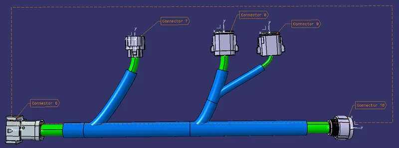
Creating Geometrical bundle in Harness A and Harness B from the given image:
Harness A:
Harness B:
Put both Harness A and Harness B in single Product:
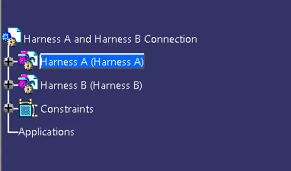
Creating Connection between Harness A and Harness B:
Just like connecting two connectors, we can connect two Harness together just by connecting the connector. So, after inserting two Harness A and Harness B in one product file,
- Go to Electric Assembly Design.
- Select command Connect Electric Devices
 .
. - Select the Connectors that are needed to be connect. In our case its Connector 5 and Connector 6.
- Make sure this connector are properly electrically defined because the connection will be done automatically.
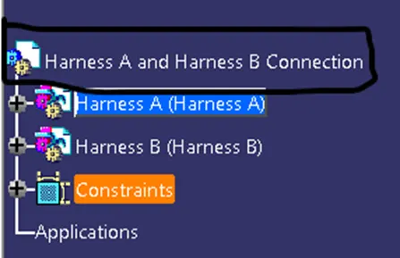
Note: Connecting two connectors should be done in main assembly, in our case “Harness A and Harness B Connection”.
Check for the Bundle Connectivity:
It is very important to check bundle connectivity because it will ensure that the connection is properly done and all wires are properly connected to each other.
To check Bundle Connectivity:
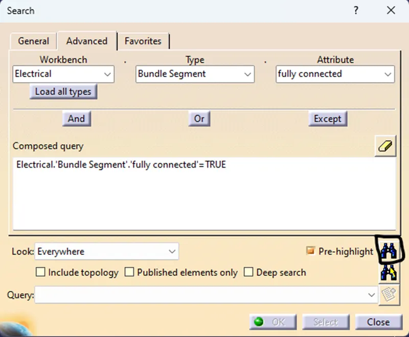
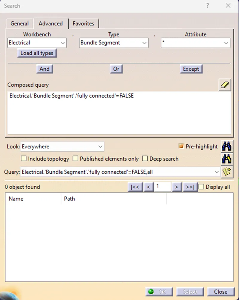
- Go to Edit>Search or press ‘CTRL+F’, this will open dialog box.
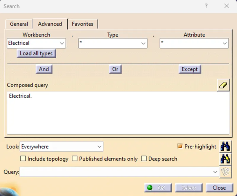
- Go to Advance section
- Select Workbench>Electrical, Type>Bundle Segment, Attribute>Fully Connected. After selecting fully connected it will open another dialog box.
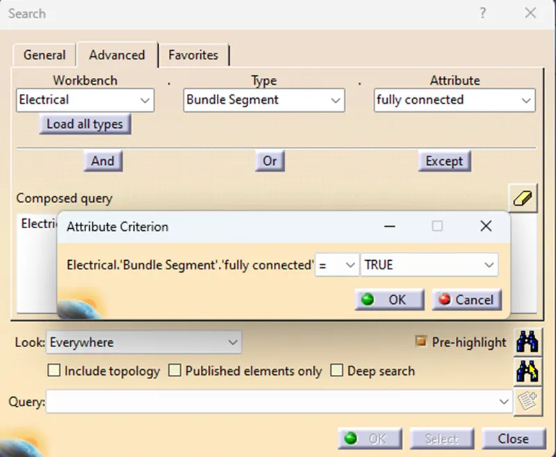
- If we select TRUE in Attribute Criterion all connection will be shown.
- Press Ok. And select Search.
- Select the harness which is need to be checked. In our case we will check the complete connection, Harness A and Harness B connection.
- Select Harness A and Harness B Connection.
- This will show all the electric device that are connected together in different Dialog box.
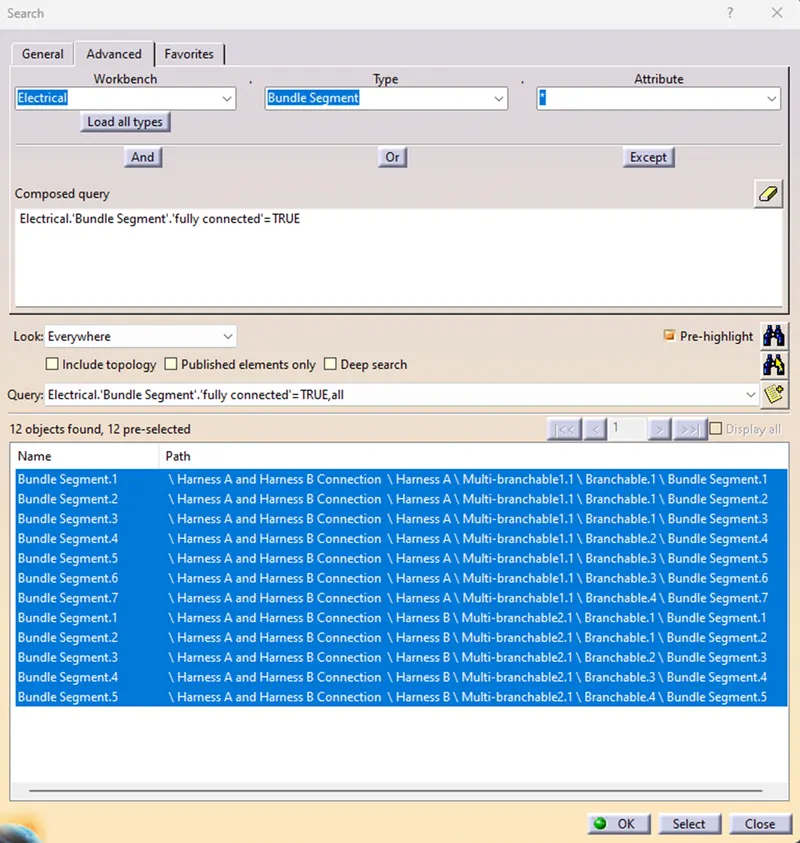
Here, we can see all the connection are properly made between the Harness or not. Here, we can see all the connection are properly made.
- If we select FALSE in Attribute Criterion all non-connection will be shown.
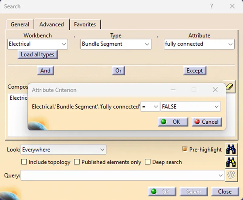
- It will show all the device that are not connected with each other in dialog box.
As, we can clearly see that all the connection is properly done between Harness A and Harness B and also together.
Adding Annotation to the assembly:
We can also add Annotation to the assembly design. As, we can see that there are many connectors are added in assembly it is hard to identify the connectors. In this case we can add different ‘Annotation’ to the assembly for clear understanding.
- Go to mechanical ‘Assembly Design’.
- We will find a Annotation Toolbar in Assembly Design
 .
. - Select View From Reference
 .
. - Now, select the plane surface or plane on which Annotation need to be placed. It is necessary to place Plane for Annotation.
- Select any option for Annotation.
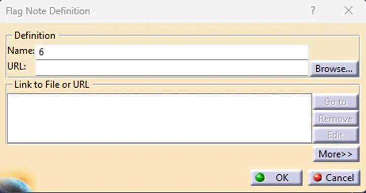
- Select the part for the Annotation and write the required Annotation in dialog box.
- Press Ok.
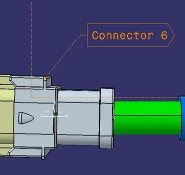
- This is how Annotation looks like.
Bundle Warning:
If, any wiring is not done properly or the wiring which is done is not properly it will shows in red color and it can be handle by either changing the position of the device or by changing the bundle parameter. Here, the example of Bundle Warning.
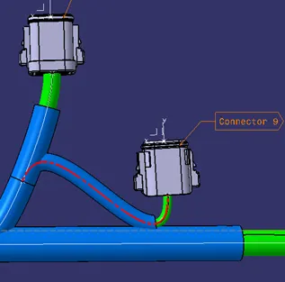
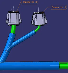
Converting the Product file in CATPart.
It is necessary to convert harness assembly to CATPart file so that other person or designer can insert it into other assemblies and can be open in different software’s also. All software’s can not open all parts so, we have to convert assembly file to CATPart file.
- Go to Tool>Generate CATPart from Product.
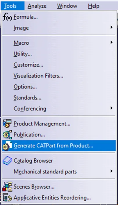
- Select the file that is needed to be convert to CATPart.
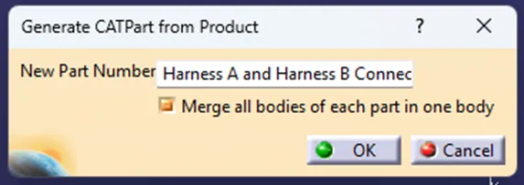
- This will convert all the file to CAD part and all electric properties will be removed. This is how CATPart file looks like.
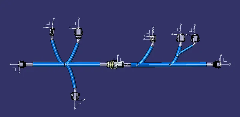
- Save this file using ‘Save As’.
- We can give the required extension to the file. In our case we had choose .igs format.

Conclusion:
The Harness A and Harness B are successfully electrically connected with each other. Also, all the required parameter are checked for the proper connectivity like Bundle Connectivity, Bundle Warning and also the CATPart file in .igs format created.