Wiring harness design in CATIA V5 - 3D modeling Week 5 & 6 Challenge
Title - Route two electrical harnesses as per the given layout and interconnect them as a single harness assembly.
Objective -
- Check the bundle Continuity. Add snap of result in submission
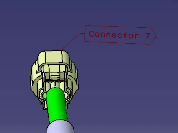
- Add annotation to all connectors. Make an assumptions for annotations like connect 1 , 2 etc
- Check for the bundle warning. Add snap.
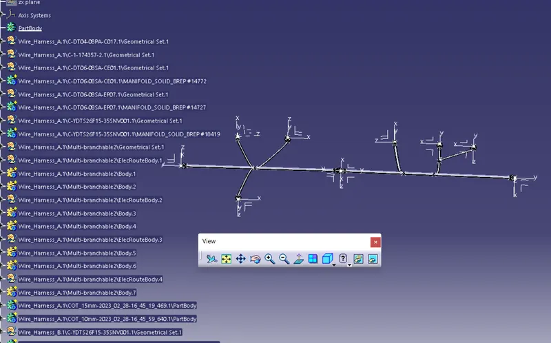
- Generate CAT.part of harness assembly and convert is in. igs format.
Design Methodology:
1.Define all connector as electrical components.
2.Preparation of Harness Assembly
3.After routing two harness make them as one harness.
4.Give proper annotations for the connectors.
5.Covert into .igs format.
1.Defining Connectors -
- First open the 3D CAD data in Catia and then convert the file format(ex: .igs,.stp) to .CATPart.
- Then define the connector geometrically in the Catia Part Design Workbench. To do that we have to first assign a mid-point to the bundle connection side face of the connector and then we also have to assign a mid-point to connector connection side of the connector, along with that we also have to assign an axis system on the mid-point of the connector connection side face. This will allow us to fully define our connector geometrically.
- After that start the Electrical Part Design Workbench in Catia to define the connector electrically.
- First we select the define connector option from the toolbars and then we select the connector body and also assign the number of terminals to the connector which in this case are 8 terminals.
- Then we select the define bundle connection point option from the toolbars and then we select the connector body, bundle contact face for representation, mid-point for point, and again bundle contact face for initial condition and then click on ok.
- Lastly we select the define connector connection point option from the toolbars and then we select the connector body, mid-point for representation, contact face for contact, Y-axis for coincidence and X- axis for orientation and then click on ok. This will fully define our connector electrically.
- Save the file.
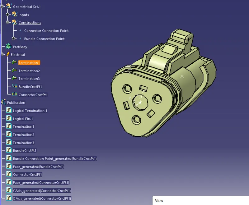
Follow the same for remaining connectors.
2.Preparation of Harness Assembly
- Create a master product file.
- Insert all the required Surrounding Part data into the Master Product file.
- Inserting Harness Components into file.
- Creating the Wire harness Geometrical Bundle
- Positioning the Inserted Components
- Defining the Wiring Harness Routing
- Switch to Electrical harness Assembly Workbench.
- Select Multibranchable Document Icon.
- In the Branch Definition Box ,describe all the required paramters like Diameter,Bend Radius(>1.4),Build mode(slack,Length,Bend,Straight Bend).
- Click Route Definition and select the two components that you need to route.
- Click OK.
- Once the Multibranchable is created, Click Add branch point command and define the point on the main branch where the Harness Branch needs to be created.
- Repeat the steps from "3 to 5."
- Add protective covering on the required branches by using Protective Covering Command and mention the start and end extremity points.
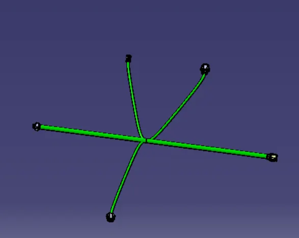
3.Make them as one Harness -
Connect and Disconnect Electrical Devices -
- If there are any assembly that need to be assembled before routing like Connector with Mounting Clip or Connector with backshell. Then Assemble them using "Connect Electrical" Devices

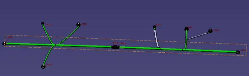
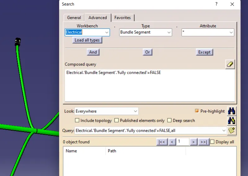
4.Giving Annotations -
With the help of Annotation tolbar we can give proper annotations.
5.Covert into .part file.
Conclusion -
Succesfully routed two electrical harnesses as per the given layout and interconnect them as a single harness assembly.