Wiring harness design in CATIA V5 - 3D modeling Week 5 & 6 Challenge
Harness A :
- All the connectors were electrically defined.
- Then they were stored in the catalog.
- The following 2d geometry was created for the positioning of the connectors:
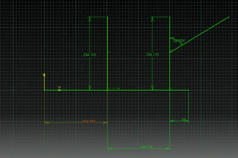
- Now in the mechanical assembly, the connectors were placed in the required positions with reference to the geometry created.
- The assembly was then converted to electrical assembly using the geometrical bundle command.
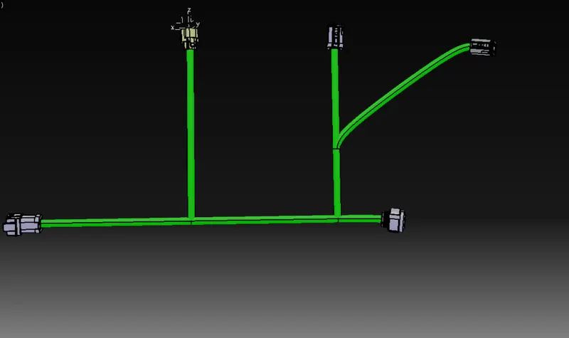
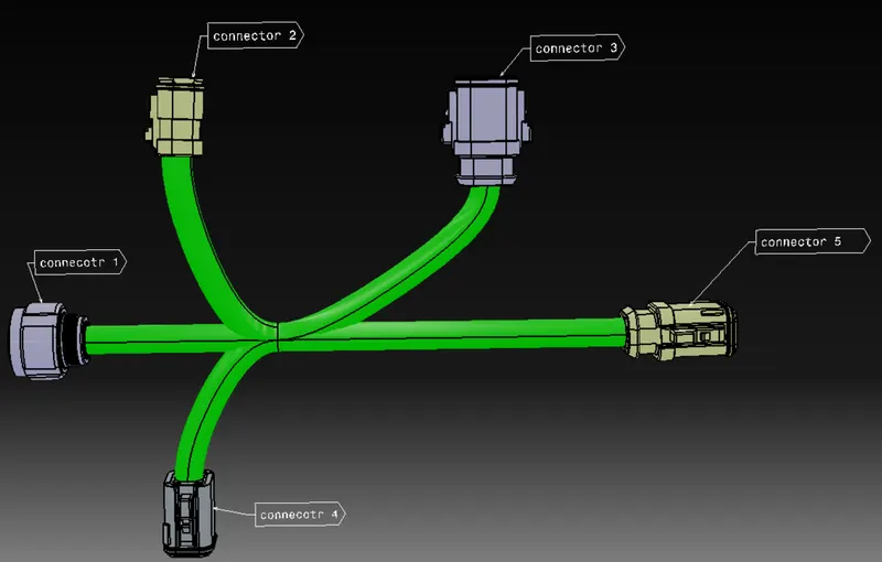
- Using the multi-branchable document command, the main routing was done with a bundle diameter of 10 mm and other appropriate parameters.
- Then placing the branch point using the add branch point command, the branches were made using multi-branchable document command with a diameter of 10 mm.
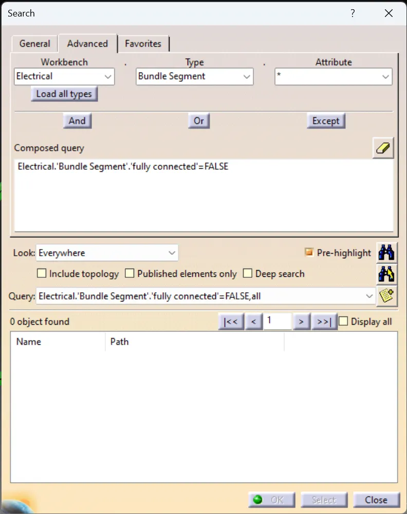
- Then in search -> Advanced -> Electrical Workbench, Bundle Segment Type, fully connected attribute = False. It is observed that 0 objects were found that are not fully connected.
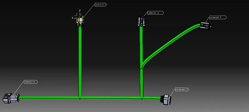
And then the annotations were added to the connectors in the mechanical assembly workbench.
Harness B:
The same steps were repeated for the Harness B
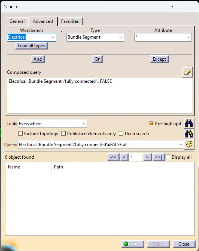
It is observed that 0 objects were found that are not fully connected.
At last, both the assemblies were converted into CATpart and then saved as igs file.