Wiring harness design in CATIA V5 - 3D modeling Week 5 & 6 Challenge
Wiring Harness Design - Harness A & B Routing
-
AIM:
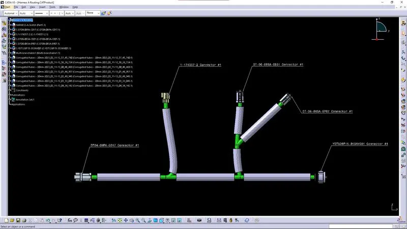
- To define the provided connectors electrically and route them as Harness A and Harness B.
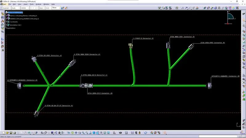
- To give annotations to both the harnesses.
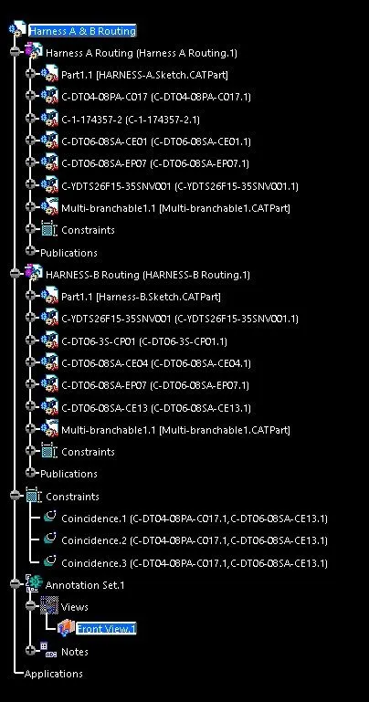
- To connect both the harnesses.
- To check bundle continuity.
-
Wire Routing:
-
Connector Definition:
This step is used to define the component electrically. This step is done in the Electrical Part Design workbench.
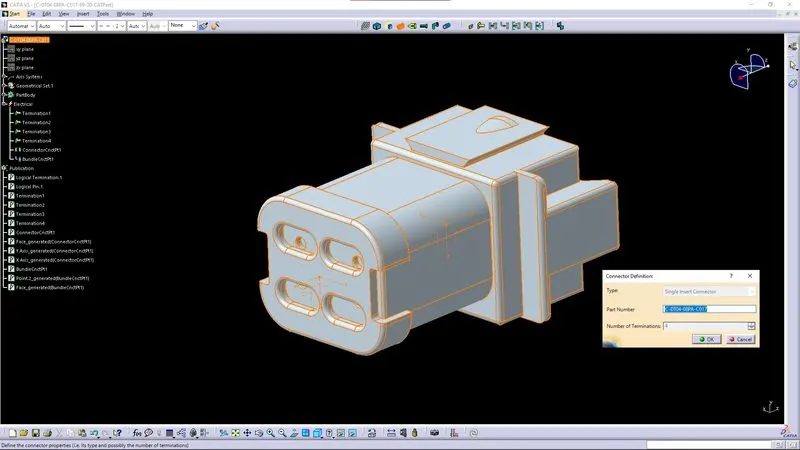
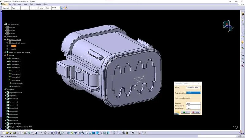
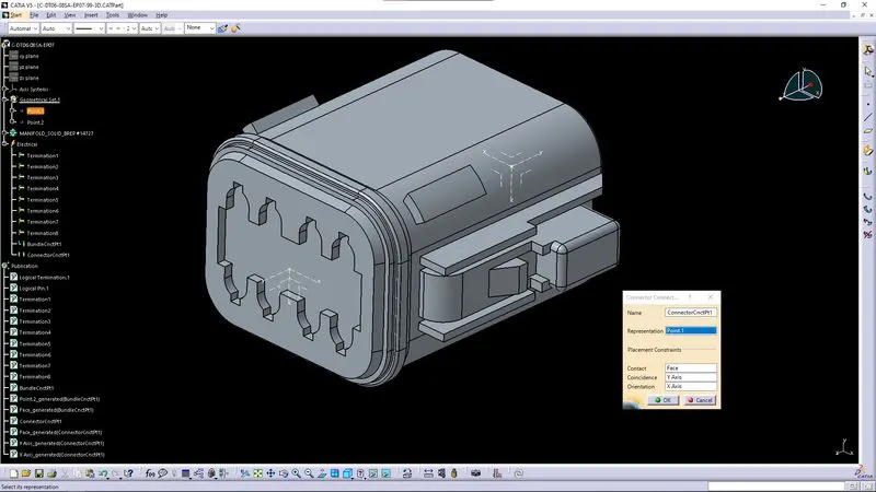
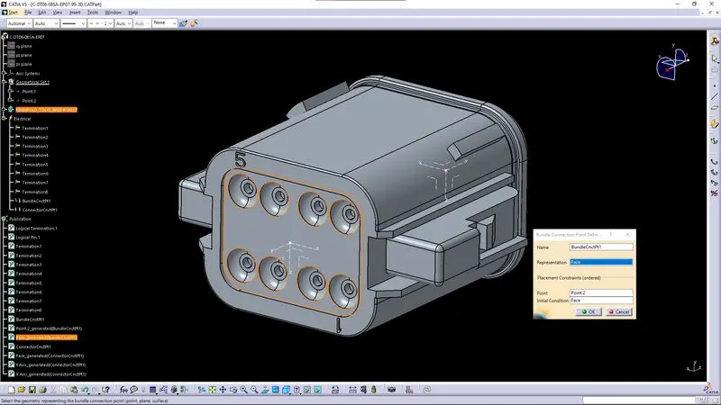
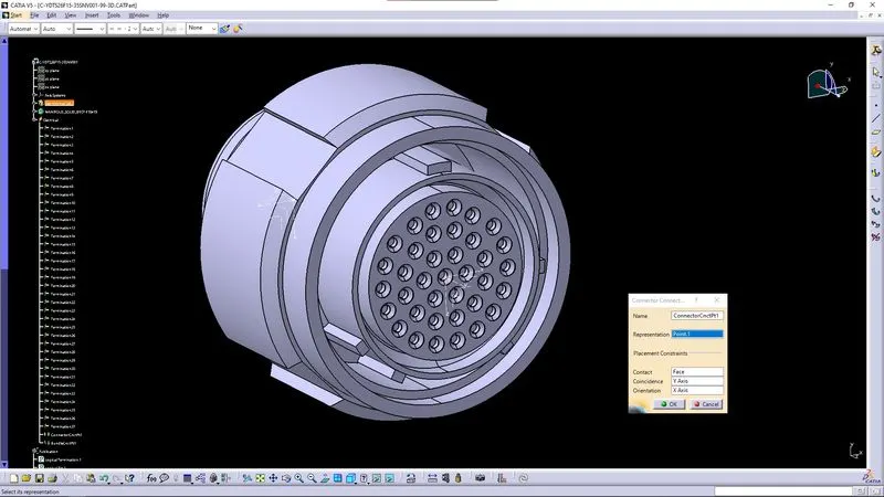
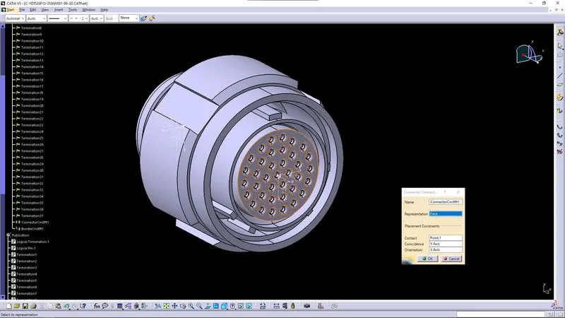
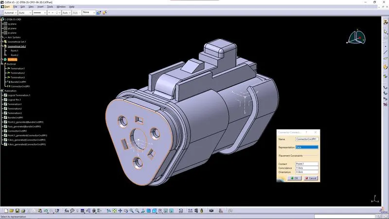
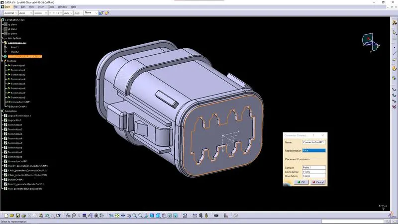
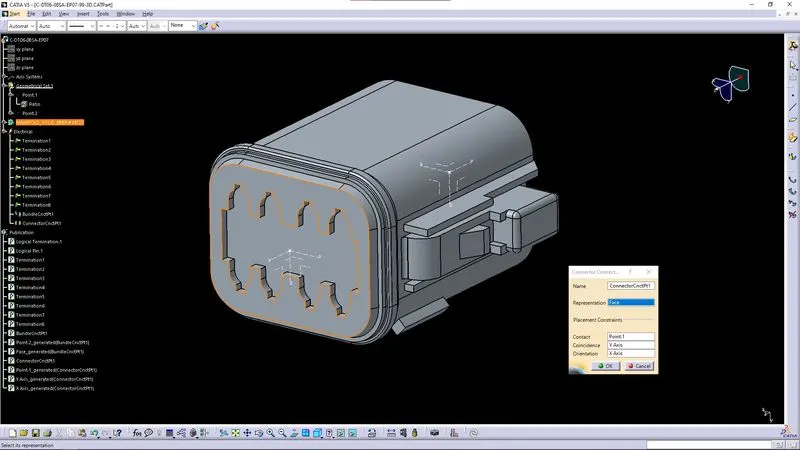
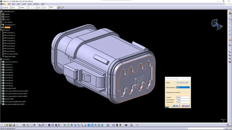
Connector Connection Point Definition:
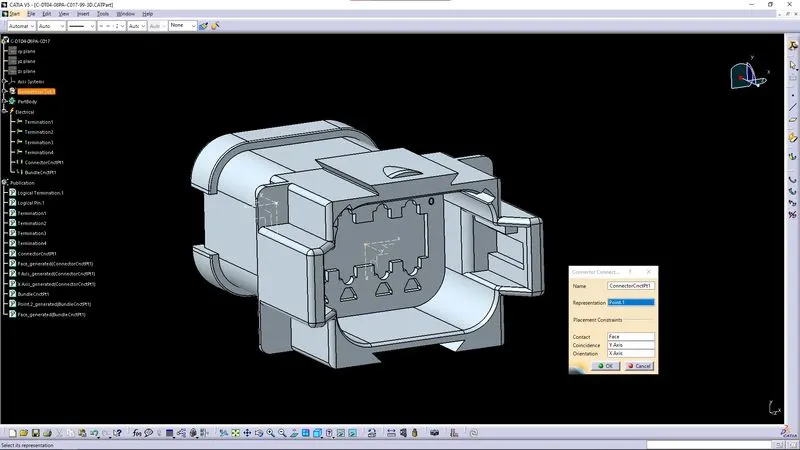
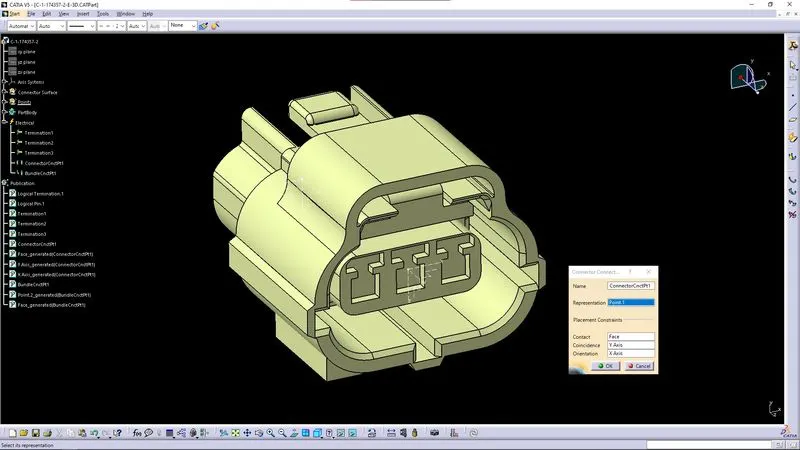
The connector connection definition process is similiar to all the variants of connectors.
- Create a point on the center for Representation.
- Insert an axis system keeping the origin as the point, where X axis is parallel (90 or 180deg) to the face of the connector and Y axis perpendicular to the face of the connector.
- Contact being the outer most face of the connector.
- Coincidence being the Y axis in the Axis System.
- Orientation being the X axis in the Axis System.
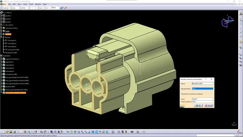
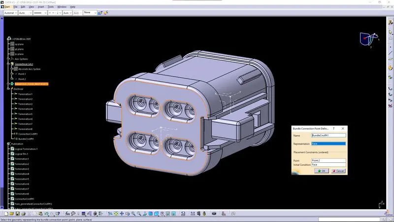
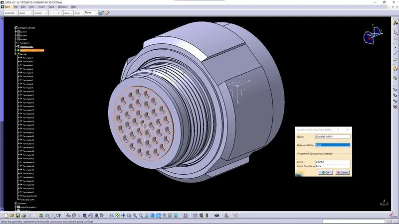
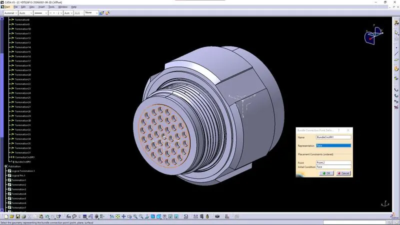
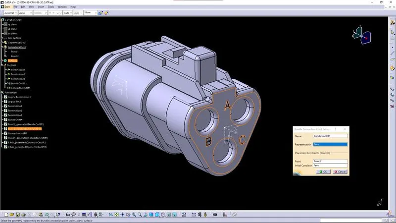
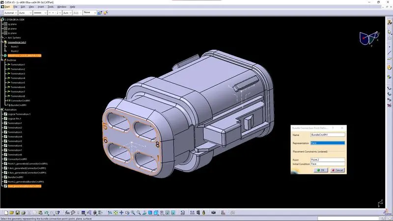
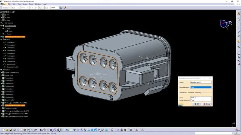
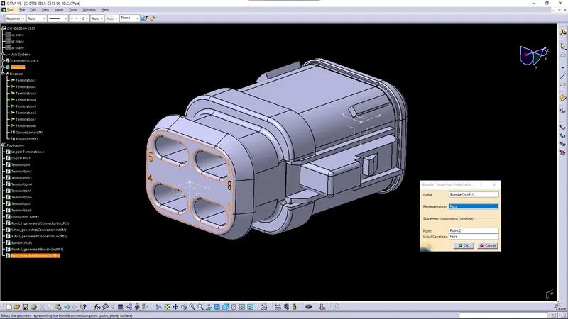
Bundle Connection Point Definition:
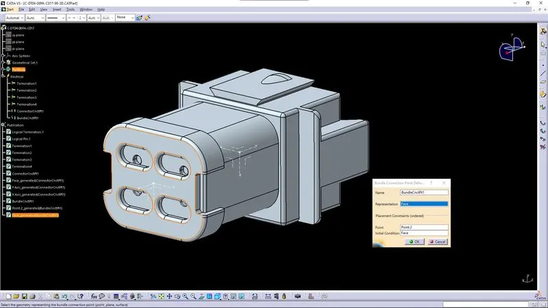
The bundle connection definition process is similiar to all the variants of connectors.
- Create a point on the center for Representation.
- Insert an axis system keeping the origin as the point, where X axis is parallel (90 or 180deg) to the face of the connector and Y axis perpendicular to the face of the connector.
- In the placement constraints, point is selected as the same.
- Initial condition being the face of the bundle connection.
Harness A Routing:
Connectors:
6.
7.
8.
9.
10.
HARNESS A:
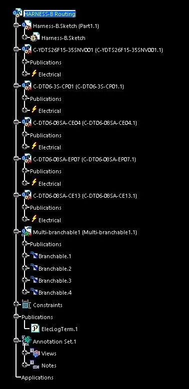
- - -
Harness B Routing:
Connectors:
1.
2.
3.
4.
5.
HARNESS B:
-
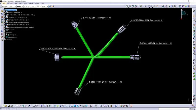
HARNESS A & B:
- - -
CONCLUSION:
- The provided connectors were defined electrically and routed them as Harness A & Harness B.
- Annotations to both the harnesses were given.
- Both the harnesses were connected.
- Bundle continuity was checked.
- - -