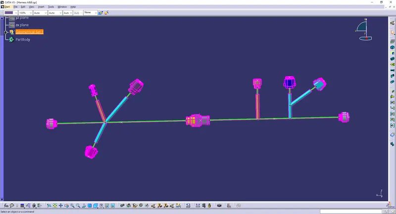
Wiring harness design in CATIA V5 - 3D modeling Week 5 & 6 Challenge
Procedure :
1. First provide the necessary properties to all the connectors like connectors connection point and bundle connection point as shown below.
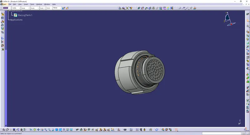
Image : Defining connector connection point
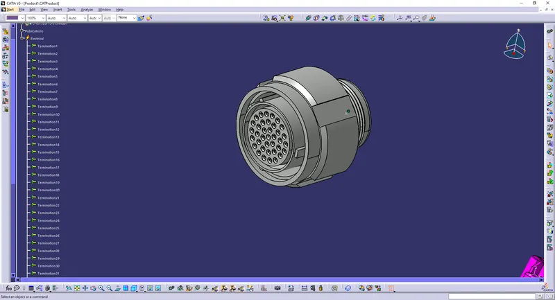
Image : Defining bundle connection point
2. Now route the harness A & harness B as per the given layout, seperately.
3. To route the harness assembly create a new product file and save as geometrical bundle A. In the assembly design workbench select existing components command and open all the connectors inside the main product file. Make sure that all the components are electrically defined before inserting all the components.
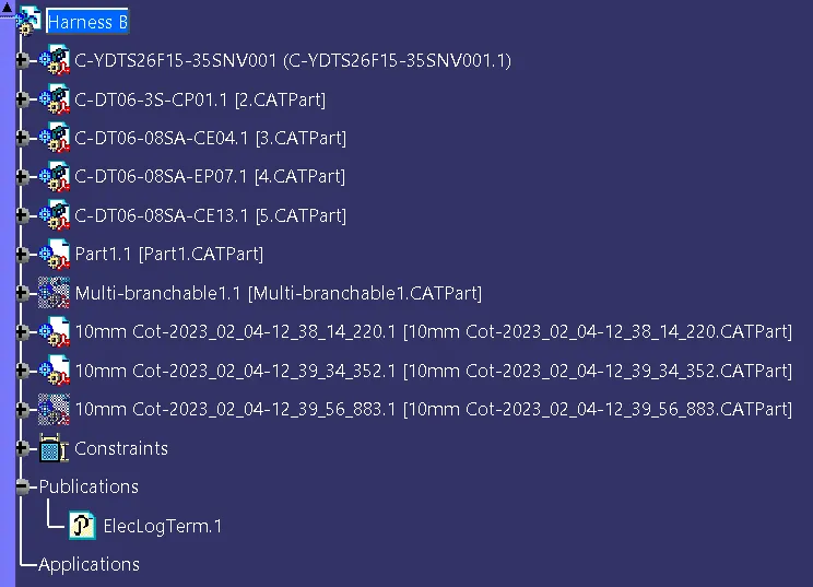
Image : Geometrical assembly Product
4. Position all the electrical parts as per the layout using manipulation tools.
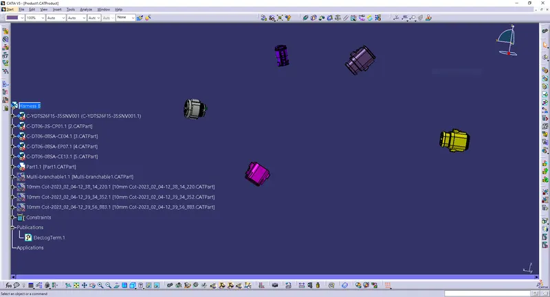
Positioning of connectors
5. Go to electrical harness assembly workbench. Click on the geometrical bundle A in the model tree and select the geometrical bundle command.
6. Select multibranchable command to create the main branch and define bundle diameter in the branch definition, select route definition and define the connectors for the main branch and click ok.
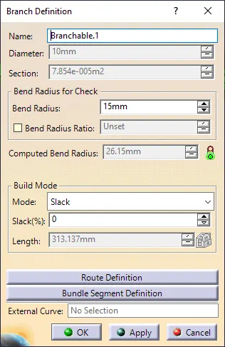
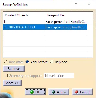
Image : Route definition
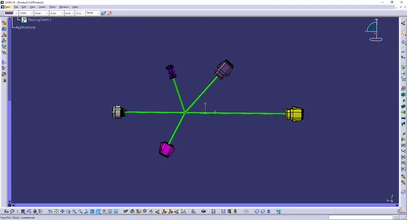
Image : Main branch
7. Double click on multibranchable created in the model tree, and you will enter electrical harness installation workbench.
8. Add branch points wherever necessary using add branch point command and create branches using branch definition command to finish the harness assembly.
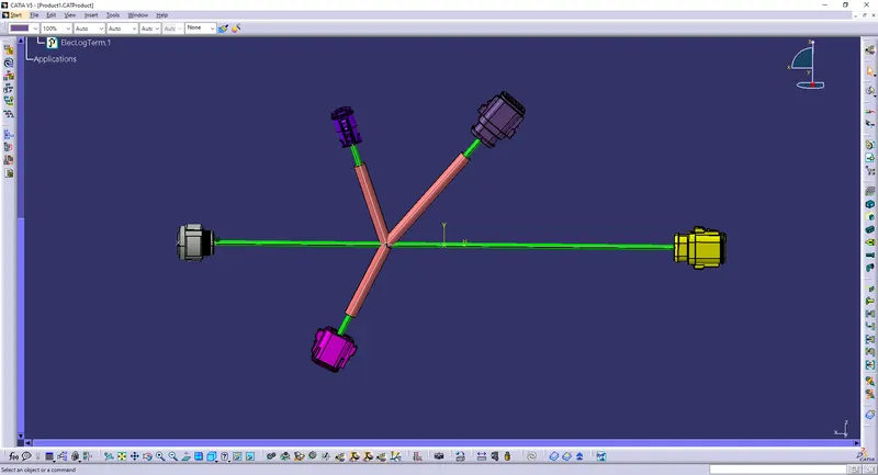
Harness B layout
9. Follow similar process for creating harness A layout.
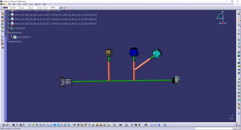
Image : Harness layout B
10. Now create new product named harness assembly A & B layout, and add harness assembly A & harness assembly B created before. Manilpualte the harness at the required positions.
11. Go to electrical harness assembly workbench and use connect electrical devices command to form connector connector connection & form the main harness layout.
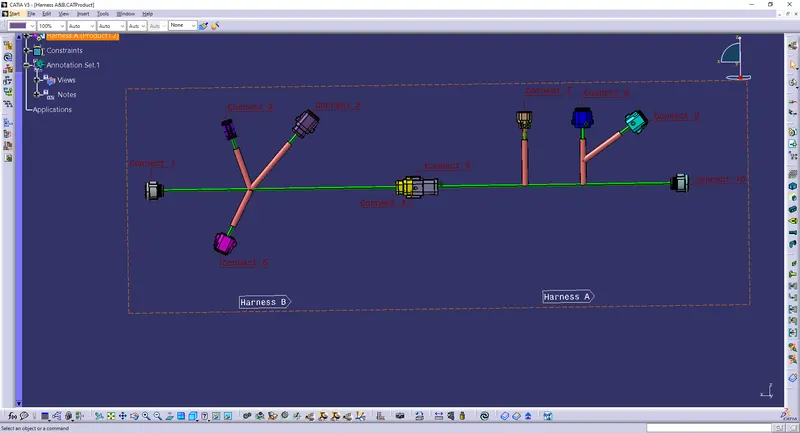
Image : Harness layout A & B
Image : Harness layout A & B
1. To check Bundle continuity
1. To check bundle connectivity, highlight multibranchable to go to electrical harness installation workbench.
2. Go to edit, go to search, select advanced tab and define workbench as electrical, type as bundle segment and attribute as fully connected and attribute criterion as true (to check connected branches) or false (to check unconnecte branches).
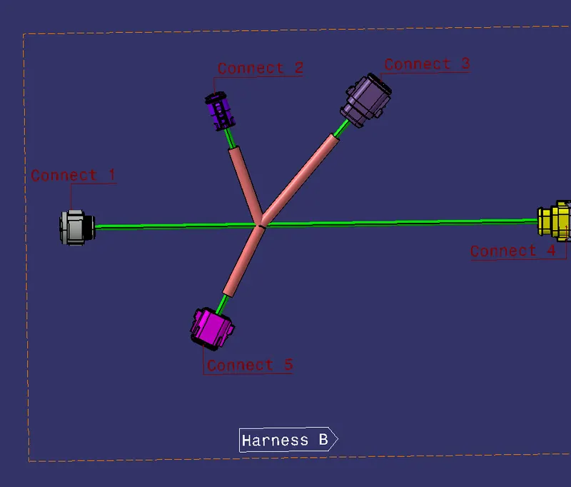
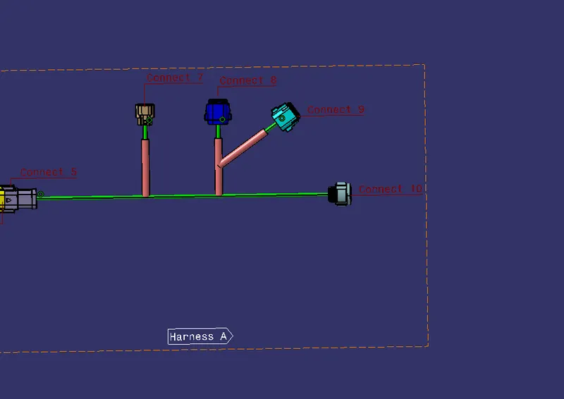
2. Add annotations to all connectors
1.Go to assembly design workbench, select view from refrence command and select desired plane.
2.Select flag note with lader command, select any point on connector, give name and click ok.
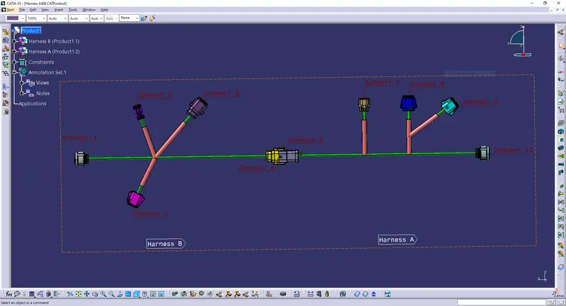
3. Bundle warnings
It is possible to get warnings when routing your wire harness, these warnings are usually displayed in the tree structure of the wire harness geometrical bundle.
These warnings are related to bend radius, bundle dia and vector position of your bundle segments.
Resolution is done by adding some extra slack if possible or by changing the vector position of the segment point depending on the route of bundle segment.red colour branch or yellow icon in the branchable segment shows bundle warnings.
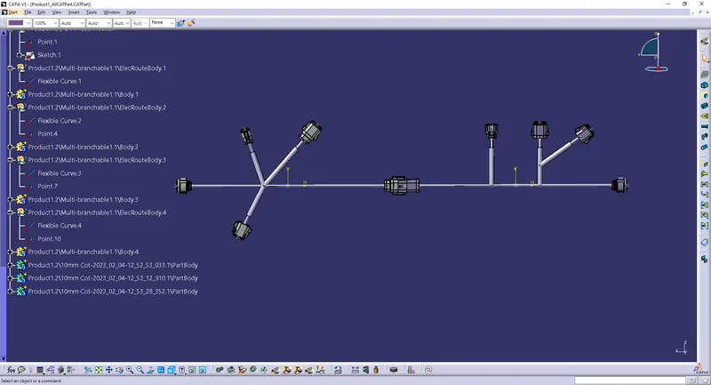
4. Generate CAT.part of harness assembly and convert it in .igs format.
Go to mechanical assembly workbench, go to tools, and select generate CAT part from product and go to files, save as and save it as .igs file.
Saved file is attached below
igs file: