Wiring harness design in CATIA V5 - 3D modeling Week 5 & 6 Challenge
AIM
Route the following harness layout in Electrical workbench. Make assumption for harness bundle diameters. Use the connectors provided. After completion of routing,
- Check the bundle Continuity. Add snap of result in submission
- Add annotation to all connectors. Make an assumptions for annotations like connect 1 , 2 etc
- Check for the bundle warning. Add snap.
- Generate CAT.part of harness assembly and convert is in. igs format.
HARNESS A AND HARNESS B CREATION
Dwnloaded the CAD data of all the components to route the following harness.All the mechanical components defined electrically to route the harness.
Here we have 8 connectors. open the cad data of connectors in catia part design workbench and create the connector connection point,connector connection axis system , bundle connection point .Then Switch to electrical part design workbench and define it as a connector also define connector connection point and bundle connection point.
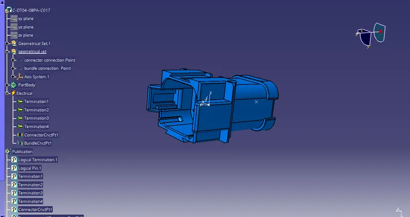
Fig.1. Connector C-DT04-08PA-C017
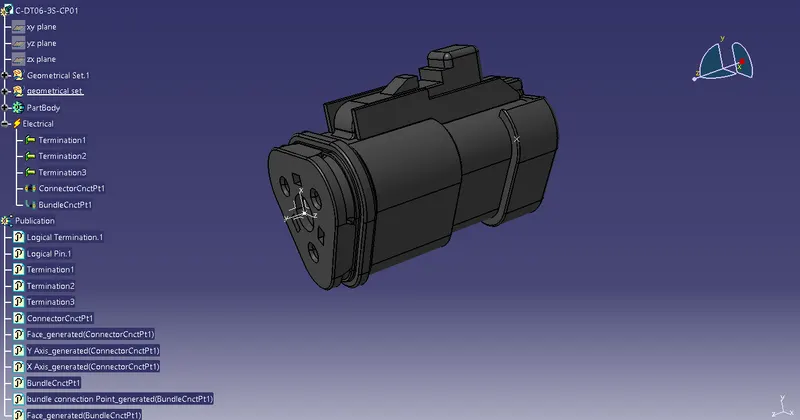
Fig.2. Connector C-DT06-3S-CP01
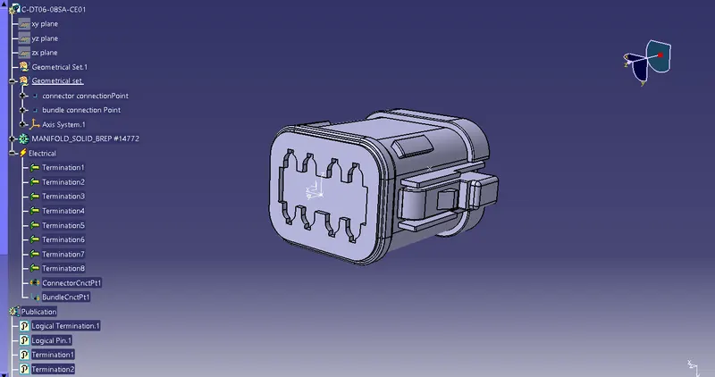
Fig.3. Connector C-DT06-08SA-CE01
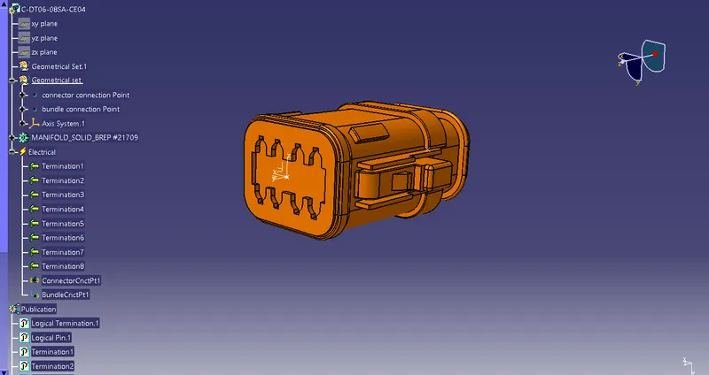
Fig.4. Connector C-DT06-08SA-CE04
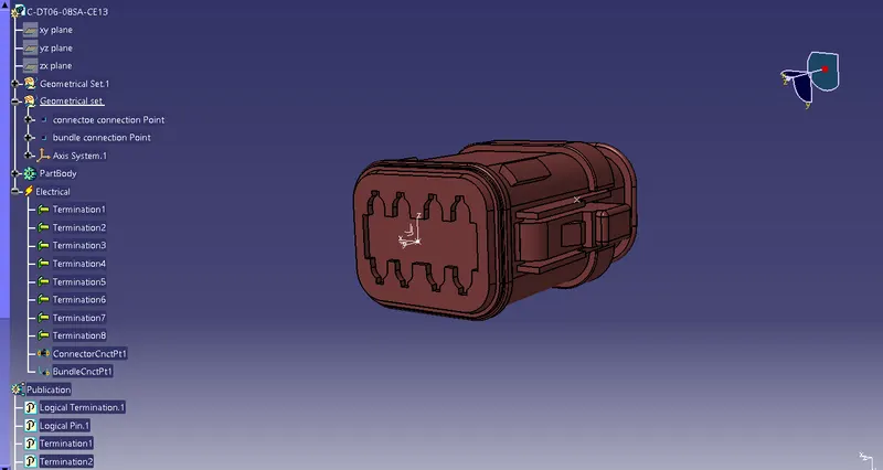
Fig.5. Connector C-DT06-08SA-CE13
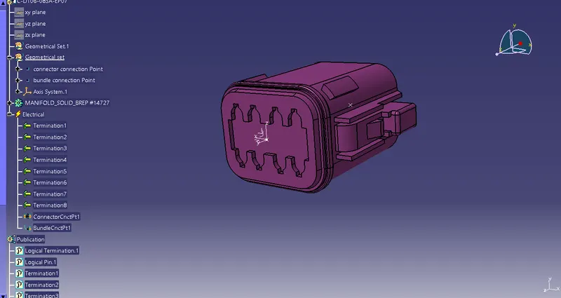
Fig.6. Connector C-DT06-08SA-EP07
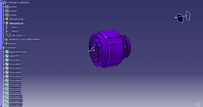
Fig.7. Connector C-YDTS26F15-35SNV001
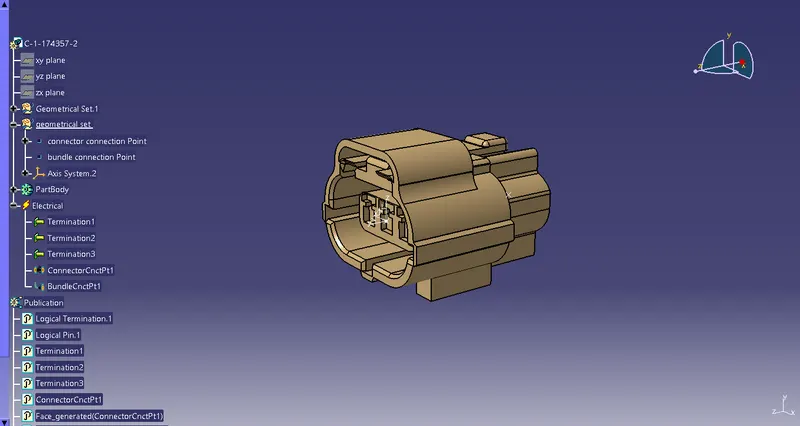
Fig.8. Connector C-1-174357-2
All the connectors defined as electrical connector and defined all the necessary properties to Connectors.
Created a catalog document in connector family and stored all the connector data in catalog document .
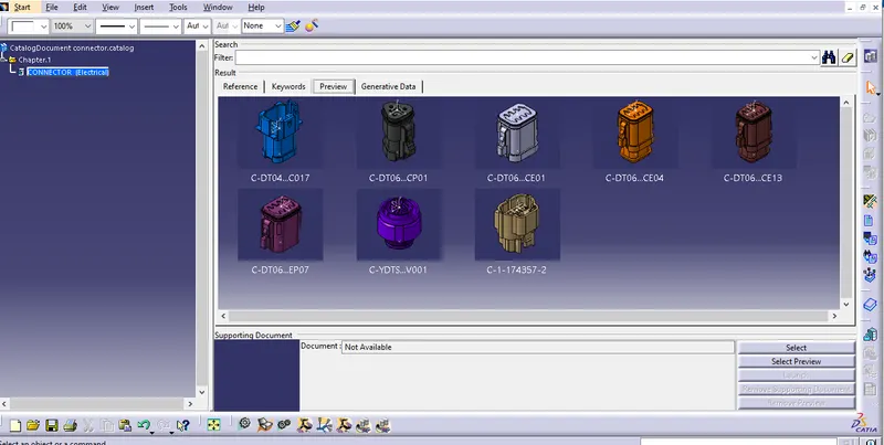
Fig.9. cataloge document
Next create a new product in assembly workbench named as assembly wiring harness contex .it is the top level product file inside this product file created geometrical bundle and wire harness electrical bundle
Geometrical bundle contains all of the harness components i.e connectors ,clip, gromets and actual physical bundle segments and branches.
Here we have 2 harness lay out , in side this geometrical bundle created two products "Harness A and Harnes B "
The required electrically defined connectors added to the harness A and harness B .Then switch to electrical harness assembly workbench and defined it as a electrical assembly by using the tool "Geometrical bundle".
All the connectors positioed based on the reference sketch by using move options((manipulation,snap,smart move, using compass etc ) in the assembly workbench .
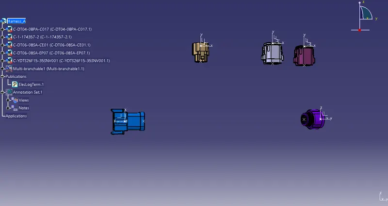
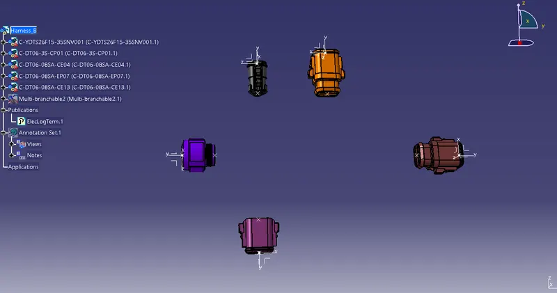
Fig.10.All components of harness A and harness B placed at desired location
bundle segment created by using the multi-branchable option in the electrical harness assembly workbench.
Multi-branchable catpart added to the harness A and B .it contains all the bundle segments and braches .first Select the diameter and bend ratio in the brach defenition window then use route defenition option and select the harness components to create the bundle .it automatically switch to electrical harness instalation workbench .
For creating sub-braches use "Add brach point" option in the electrical harness instalation workbench and select the bundle and provide required length where to create the new branch.
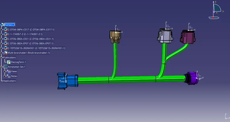
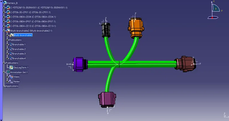
Fig.11. Harness A and Harness B
After routing the harness then check the bundle Continuity of both harness A and Harness B .
Edit⮕Search⮕Advanced⮕Electrical Workbench⮕Type:-Bundle Segment⮕Attribute:-Fully Connected.
Selecting the "TRUE" option in the attribute criterion it will show all the connected bundle segments and selecting the "FALSE" option it will show all the non-connected bundle-segments.
Here TRUE option is selected to perform the continuity check.
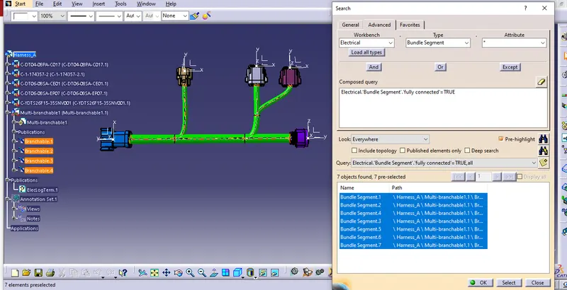
fig.12 Harness A bundle continuity check
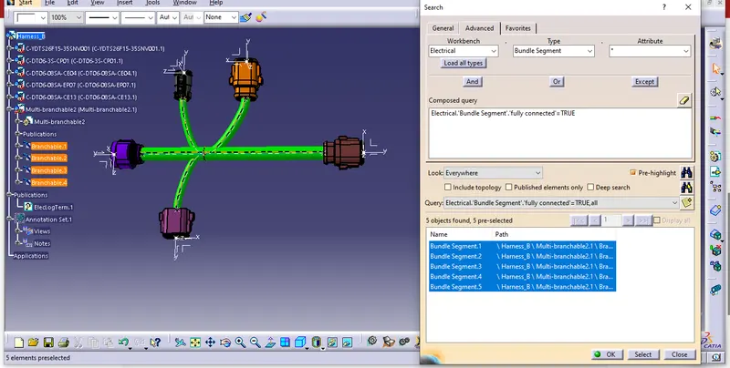
fig.13. Harness B bundle continuity check
next checking bundle warnings in the Harness A and B.
Geometrical bundle warning generated due to errors in Bend radius, Bundle diameter or Vector position.
If there is any erorr in the bundle segment the yellow indication will appear in the multi branchable cat part and also in the sub tree structure .
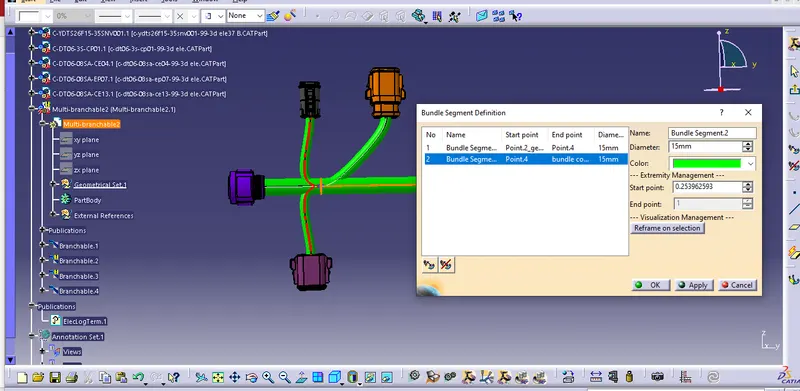
fig.14. error in the bundle segment
The above shown fig 149. the error is due to bend radius .So go to bundle segment defenition and change the brach point location to solve this issue . Depending on the routing of the bundle segment we can troubleshoot the error by adding slack or changing vector position.
Then switch to electrical assembly design workbench , use connect electrical devices option and select the connectors(connector 5 and 6) to interconnect the harness A and harness B .
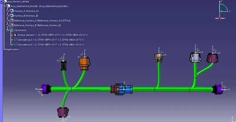
fig.15. Interconnectecd harness A and Harness B
Next adding annotations for all the electrical connectors.
Annotations are used for easy identification,informatioins of components in the harness assemby .
- select the harness A and switch to assembly design workbench to create the annotations .
- select the view from reference option in the annotation tool bar then select the required plane to create the annotation.
- Then give annotations to the electrical components by using "flag note with leader" option from annotation toolbar
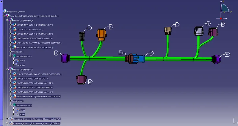
Fig.16. Annotations of harness A and B
Next step is Generate CAT.part of harness assembly and convert is in. igs format
- switch to Mechanical Assembly Workbench and select "Generate CAT Part from product" option in the tools to create the cat part
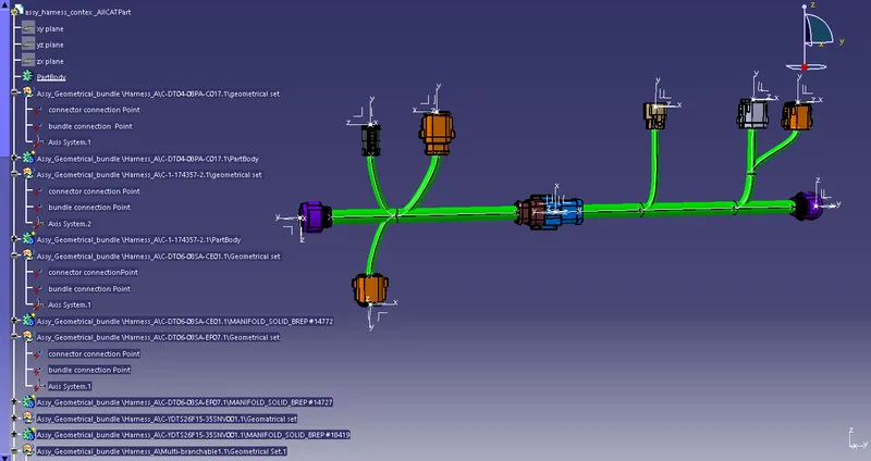
fig.17.Generated CAT.part of harness assembly
Save this catpart in the igs format by using the save as option .give the file name and select the "save as type" as .igs format
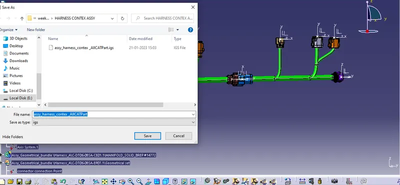
fig.18. igs file convertion