Wiring harness design in CATIA V5 - 3D modeling Week 5 & 6 Challenge
- Connectors
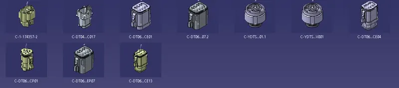
The connectors for the required harnesses are electrically defined in the Electrical Part Design Workbench.The Points,Axis,Connector connection and Bundle connection points are all defined.
- Sketch
The sketch for the harness routing path is made in the Part Design Workbench.
- Harness A and B
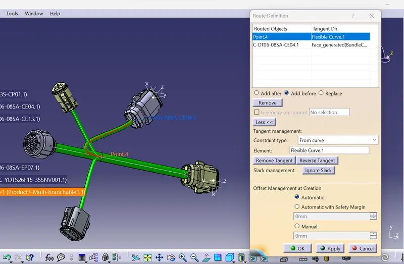
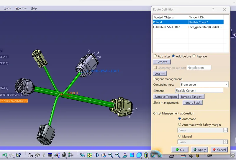
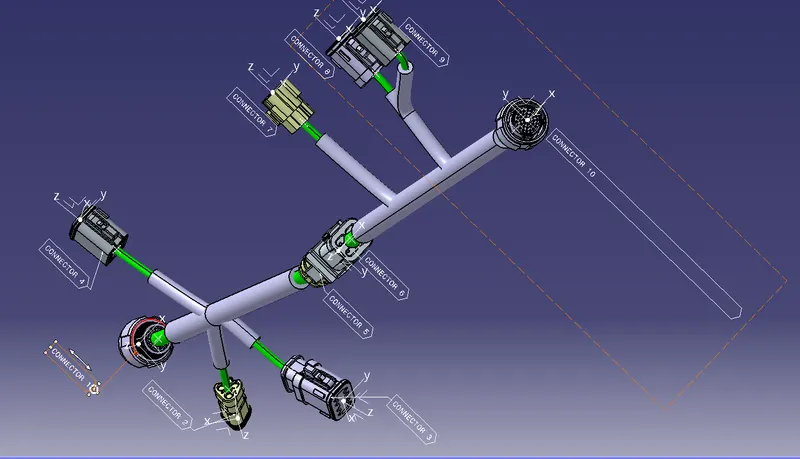
The Required sketch and the connector are bought into the Assembly Design Workbench.Use Manupulation and Snap tool to adjust the correct positions of the connectors as per the requirements.Then bring the work to the Electrical Harness Assembly Workbench and define it as a Geometrical bundle and choose Multibranchable so it activates the Branch definition icon.Define the branch between the connectors.Define the Branch Point in them and define bundles to the other connectors.The routing is made between the connectors.Define Protective Covering to the harness.Add COT tubes at the required size from the cataloque to the bundles.Save the work.Then Define a new product file in the Electrical Assembly Design Workbench and bring the two harness A and B into this.Join the two coonector of the respective harnesses by the Connector Connection Point by the icon of connect electrical devices.Then save the work.
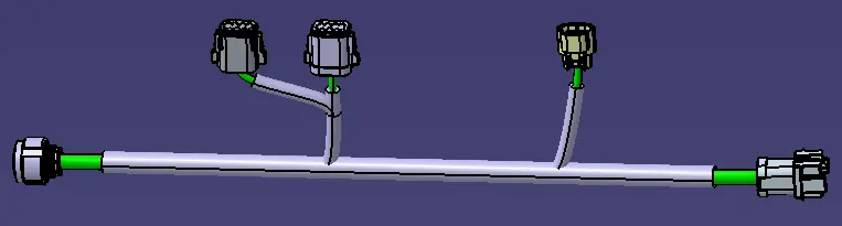
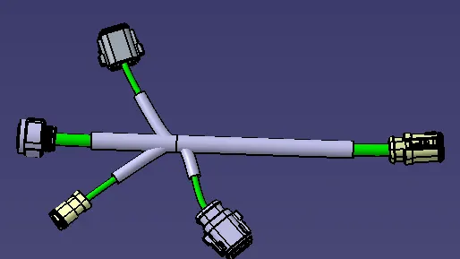
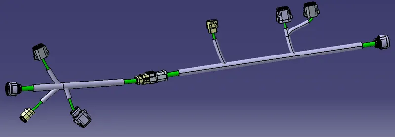
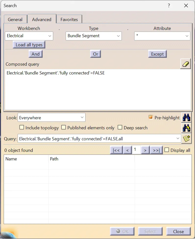
- The required Bundle Warnings appered and the required measures were taken to solve it.The required igs format files were made and attached.The Bundle Annotations are made as well as the Bundle Continuity are checked.