Wiring harness design in CATIA V5 - 3D modeling Week 5 & 6 Challenge
Week 5&6 Challenge
Objectives:
- Check the bundle Continuity. Add snap
- Add annotation to all connectors. Make an assumptions for annotations
- Check for the bundle warning. Add snap.
- Generate CAT.part of harness assembly and convert is in .igs format.
The following two wire harnesses are to be created with the help of given connectors and they need to be connected electrically in the final assembly.
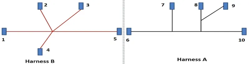
Fig: given wire harnesses and their layout
The following procedure has been adopted:
- Define geometrical parameters for all the connectors in part workbench.
- Define all the connectors as electrical parts in electrical part design workbench.
- Create the two harnesses in electrical harness assembly workbench.
- Create a new assembly file, add the created two harnesses in this file and connect them electrically in electrical assembly design workbench.
- Add annotations for all the connectors in assembly design workbench.
- Generate CAT part from product file (the harness assembly).
- Finally give the desired appearance color to this part.
Create wiring harness-A & harness-B
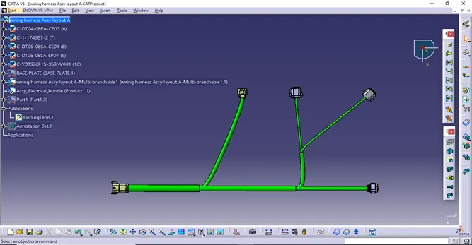
Fig.1 Harness-A
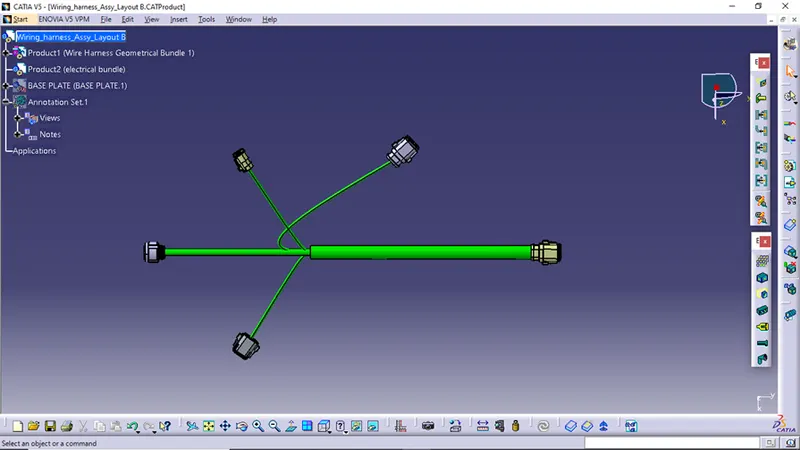
Fig.2 Harness-B
- Wiring harness-A & harness-B continuity
To check the bundle continuity.
Make sure multi-branchable is selected and then do the following
Edit>Search>Advanced>Electrical Workbench>Type-Bundle Segment>Attribute-Fully Connected.
"TRUE" will show all the connected bundle segments while "FALSE" will show all the non-connected bundle-segments.
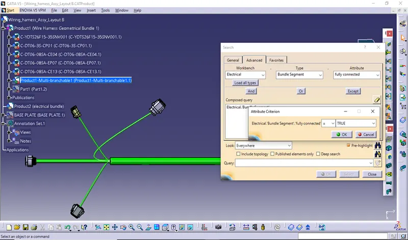
Fig.3 Checking the harness-A for fully connected
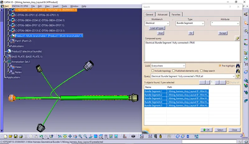
Fig.4 shows all the bundle segments are fully connected
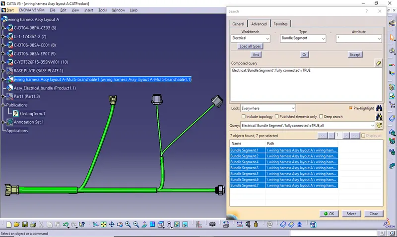
Fig.5 shows all the bundle segments are fully connected
- Adding the two harness into another product assembly file
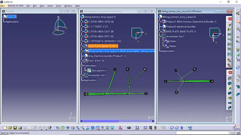
Fig.6 importing the two harnesses into a single product file
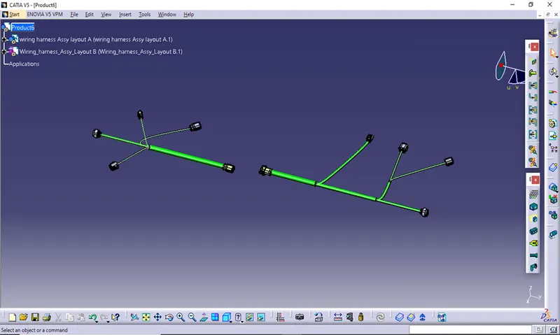
Fig.7 After importing both harnesses
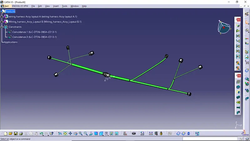
Fig.8 Assembly file after creating the electrical connections
- Adding annotations to different connectors
Mechanical assembly Workbench>view from reference> flag note with ladder>select connector>add annotation>edit properties.
Make sure that the geometrical bundle is active before choosing the annotation plane.
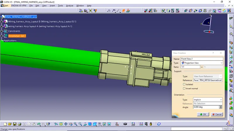
Fig.9 Adding annotation plane
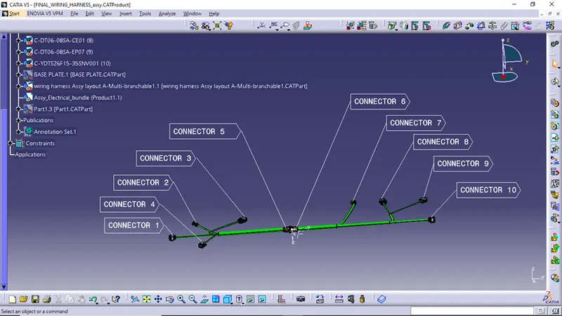
Fig.10 After adding all the annotations
- Checking for bundle warning
Geometrical bundle warnings are shown for Vector position, Bend radius and Bundle diameter.
Depending on the route of the bundle segment we can resolve the issue by adding some extra slack or by changing vector position of the segment point.
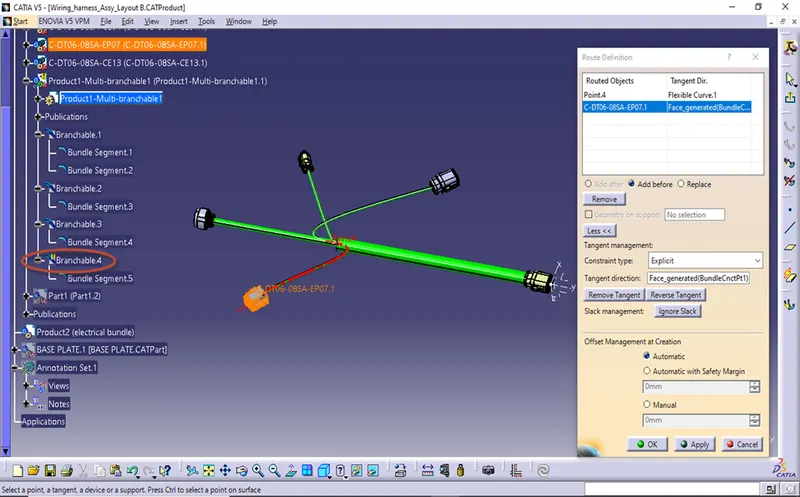
Fig.11 problem occurred due to vector position
- Creating the part file from assembly file and Saving part file in IGS format
- Mechanical Assembly Workbench>Tools>Generate CAT Part from product
- File > Save as > select folder location > in type block select “igs” > save.
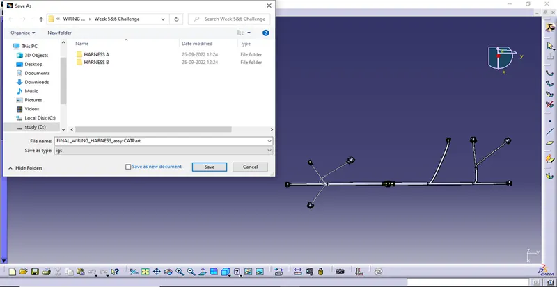
Fig.12 Saving file in .igs format
Give appearance color of your choice.
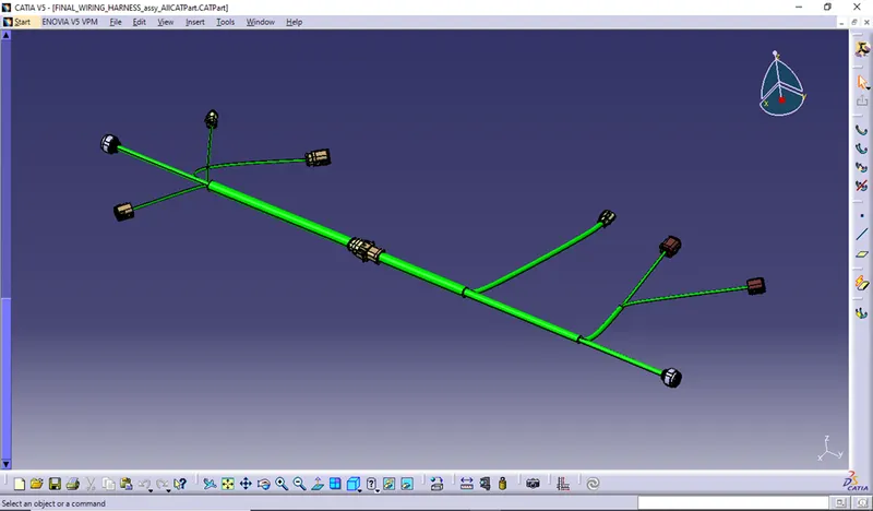
Fig.13 final part file of wiring harness assembly