Wiring harness design in CATIA V5 - 3D modeling Week 5 & 6 Challenge
We need to Download all the requied CAD 3D design from the given link.
HARNESS A
- We need to give the connector connection points and the bundle connection points to all the connectors which are given in the HARNESS A.
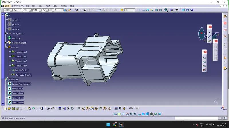
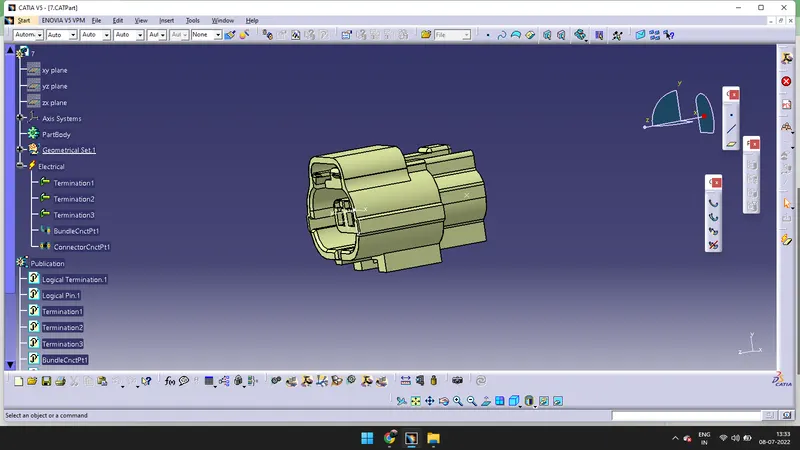
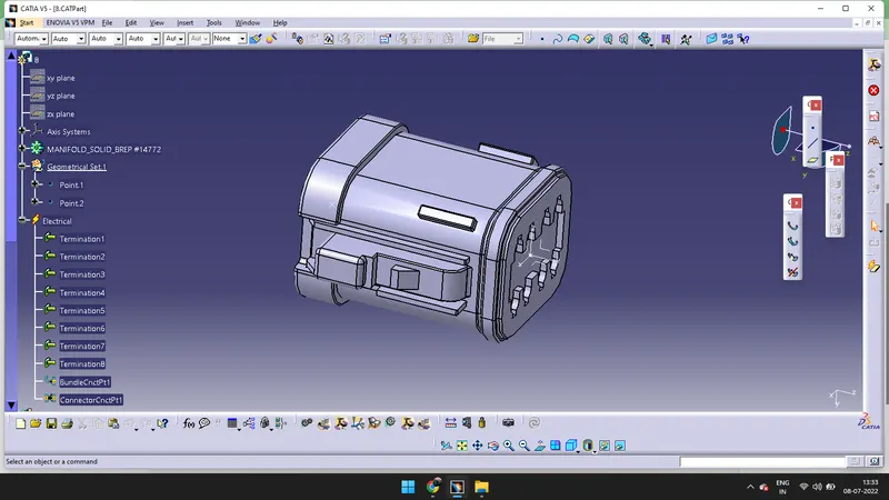

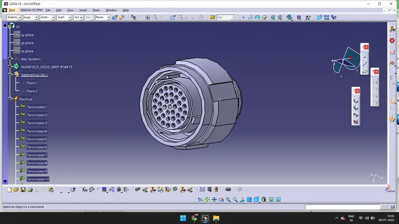
- I have created as sketch to avoid confusion it is not mandatory. We can manuplate according to the figure given in the above File.
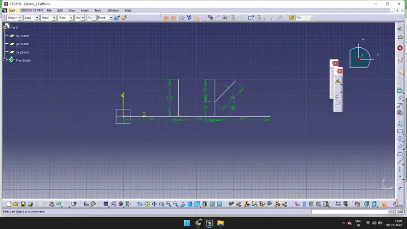
- We need to go to Assembly design and copy all the above connectors along with the sketch and past in the assembly design.
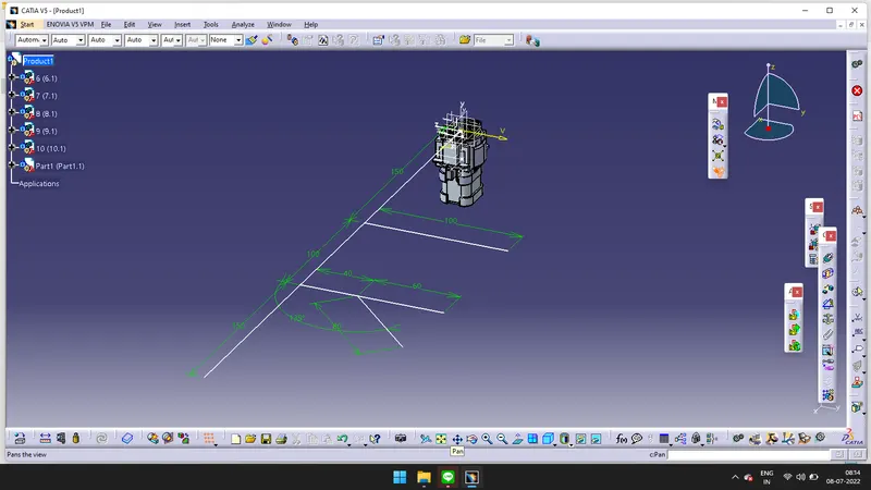
- Using manipulation command we need to manipulate the connectors.
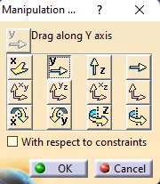
- Click on the Snap and snap the connectors according to the figure given.

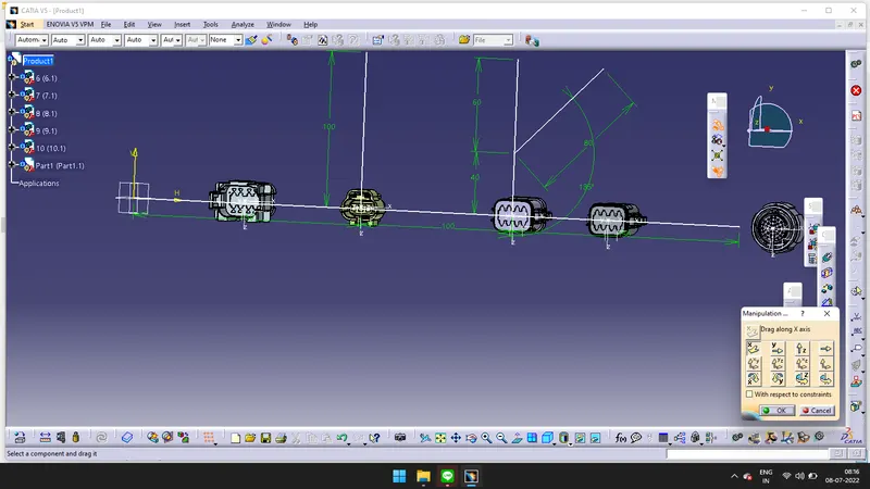
-
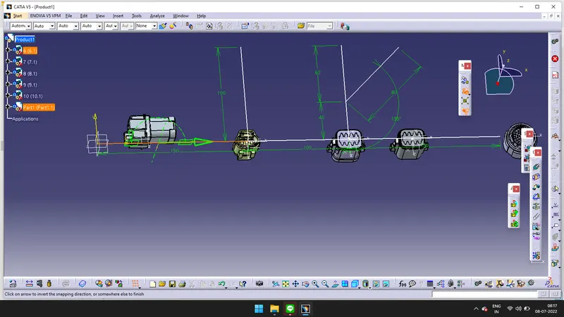
- Drag the compass and place it on the connector and rotate the connector to requied drirection.
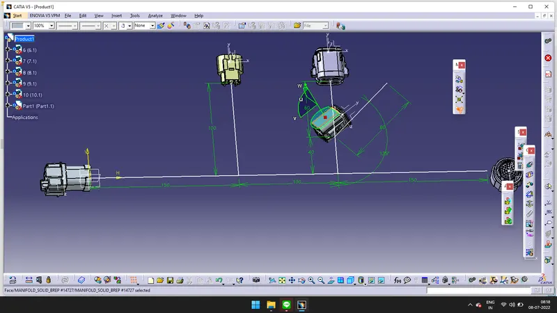
- Snapping done according to the figure.
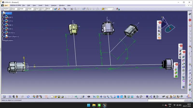
- Go to Electrical harness Assembly > click on Geometrical bundle > Doulbe click on product.
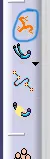
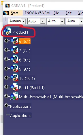
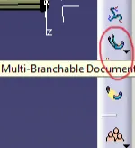
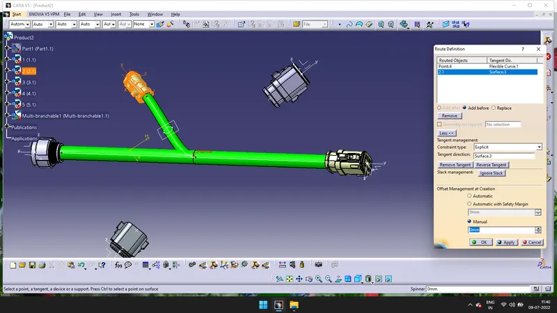
- Click on the Multi_Branchale Document > Click on the Route Definition > Click on the connectors > Click on the Reverse tangent.
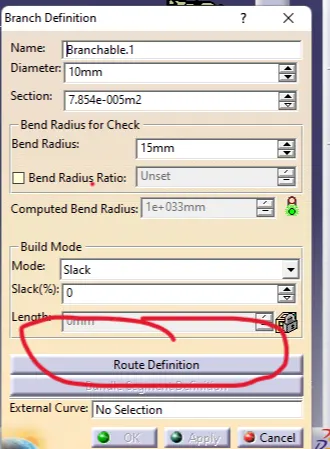
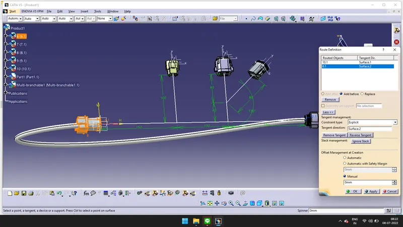
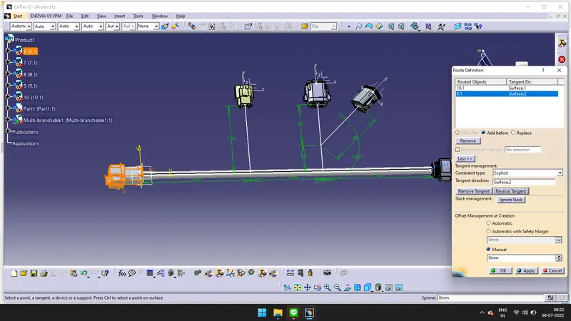
- Branch is created.
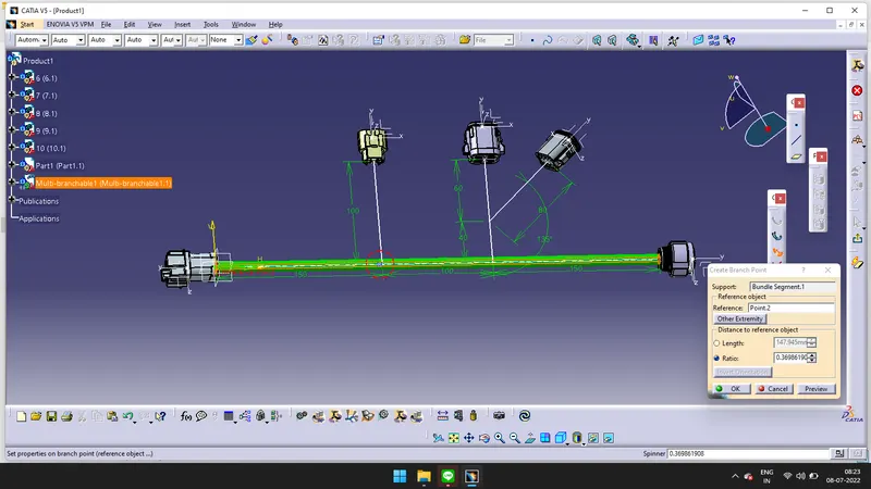
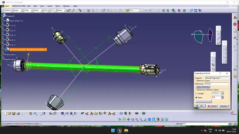
- Click on the Add Branch Point and create two points.
-
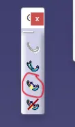
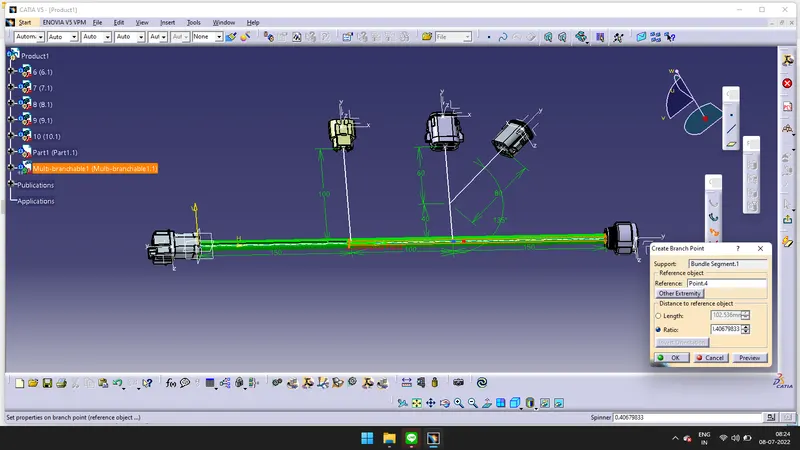
- I have used Sketch for manipulating the connectors. I made some changes in placing the connectors for routing correctly. Click on Branch definition > Click on Routing > Select the bundle and the direction in which you are routing the bundle.
-

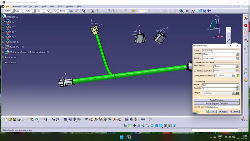
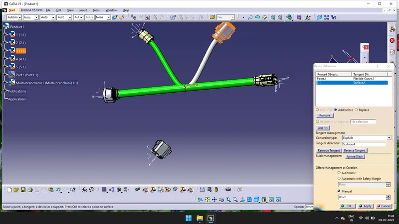
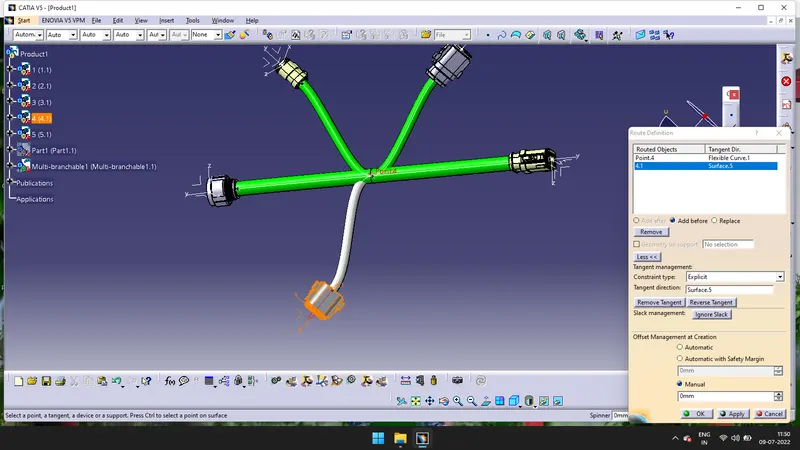
- Accordingly create Branches for all connectors. If there is need of bundle point, create a point by using Add Bundle Point command.
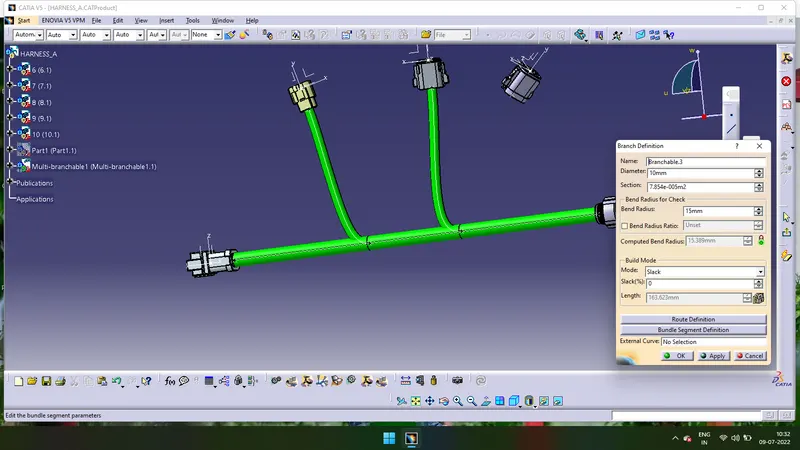
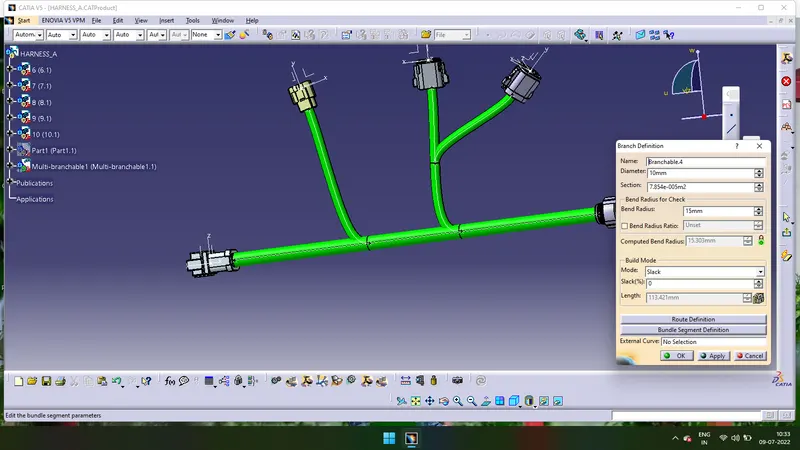
- We have completed the Harness A, according to the figure.
HARNESS B
- We need to give the connector connection points and the bundle connection points to all the connectors which are given in the HARNESS B.
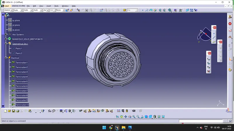
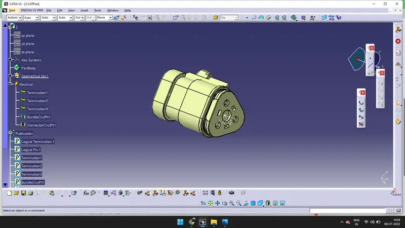
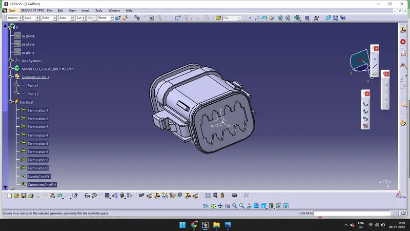
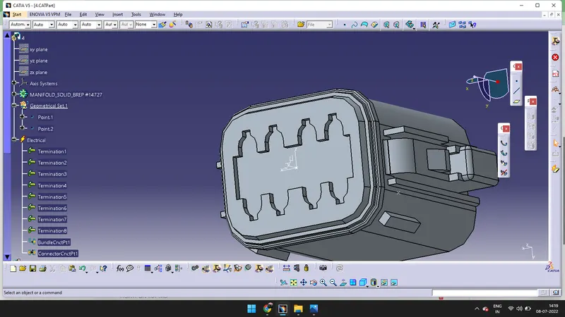
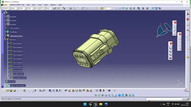
- I have created as sketch to avoid confusion it is not mandatory. We can manuplate according to the figure given in the above File
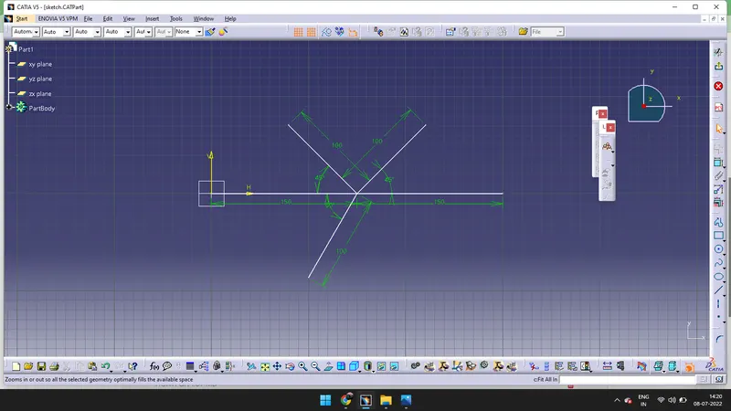
- We need to go to Assembly design and copy all the above connectors along with the sketch and past in the assembly design.
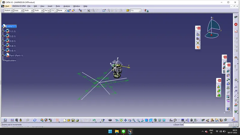
- Using manipulation command we need to manipulate the connectors.
-
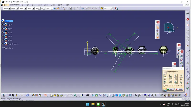
- Click on the Snap and snap the connectors according to the figure given.
-
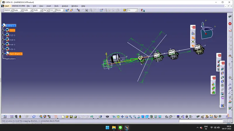
- Drag the compass and place it on the connector and rotate the connector to requied drirection.
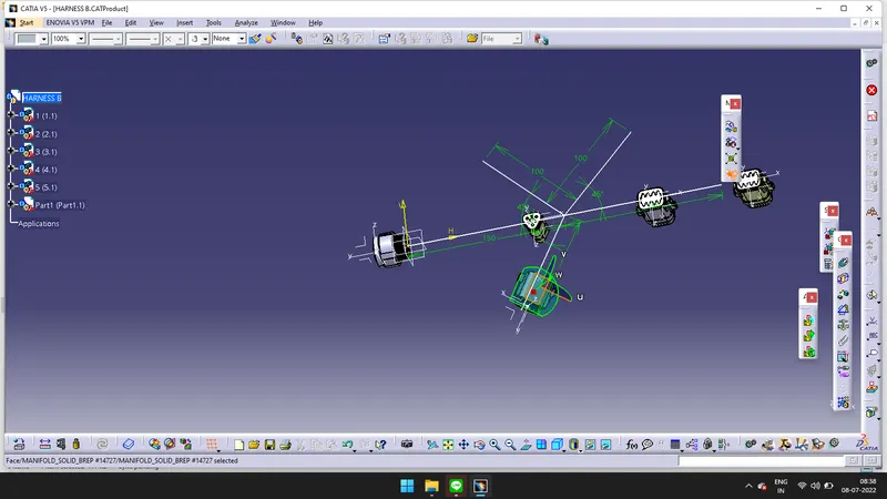
- Snapping done according to the figure(HARNESS B)
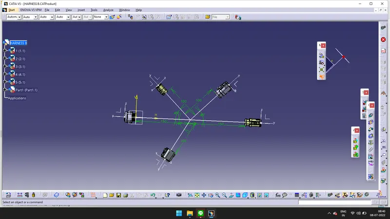
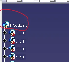
- Go to Electrical harness Assembly > click on Geometrical bundle > Doulbe click on HARNESS B.
-
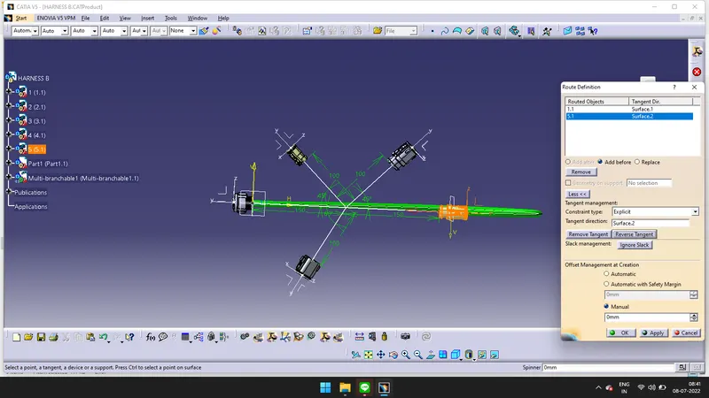
- Click on the Multi_Branchale Document > Click on the Route Definition > Click on the connectors > Click on the Reverse tangent.
-
- Follow the same steps which are used to create wiring harness in HARNESS A. Click on Add Branch Point to create Point and click on Branch Definition to create branch.
- GO to Electrical Assembly Design > Right click on the Product > Go to Components > Go to Exixting Components. Select the product or component which you want to open.
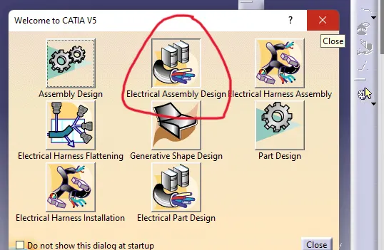
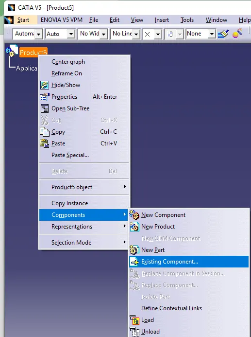
- I have selected the existing components, which I need.
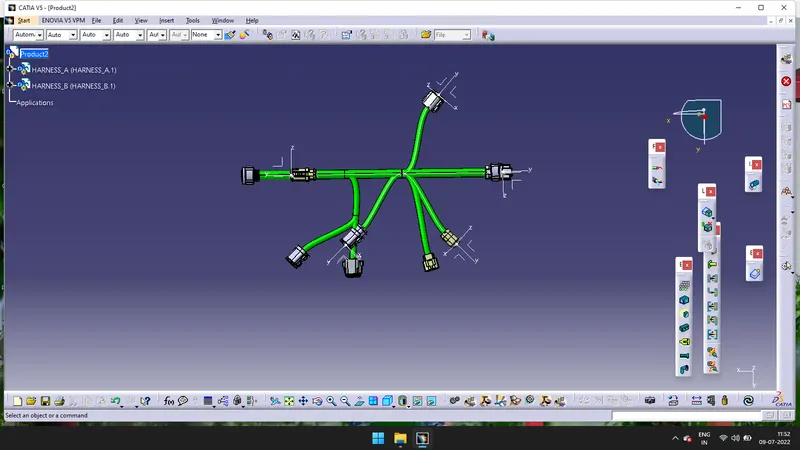
- Go to Assembly Design and manipulate the components
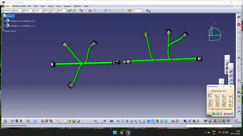
- Click on the Connect Electrical Devices command > Select the Two connectors. So they will be connected.
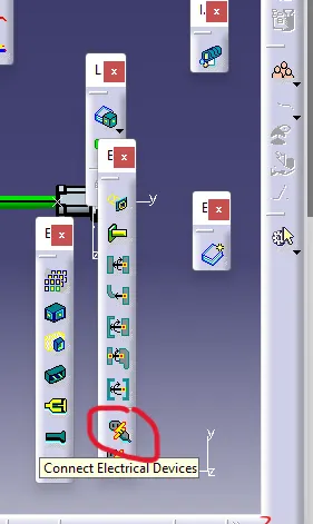
- They are c
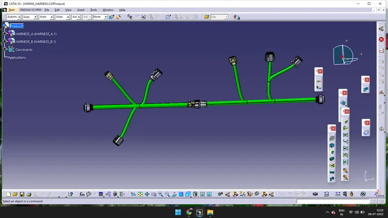 onnected.