Wiring harness design in CATIA V5 - 3D modeling Week 5 & 6 Challenge
WIRING HARNESS DESIGN IN CATIA V5 - 3D MODELLING
Aim: To route the given harness layout in Electrical workbench
Defining the Connectors
First of all, the connectors are defined by define connector command and then the connector connection point and bundle connection point have been defined. These are all done in electrical part design workbench,
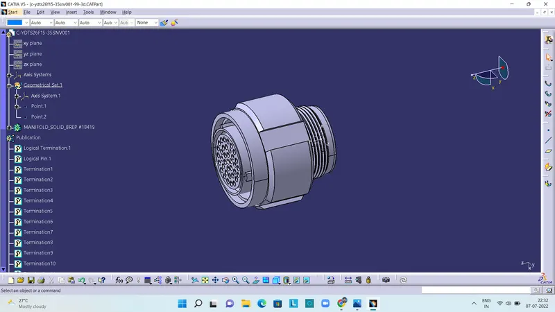
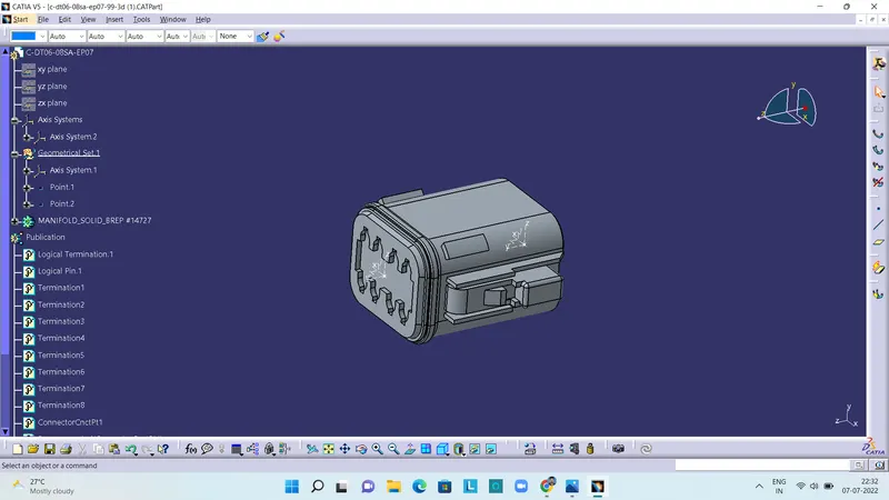
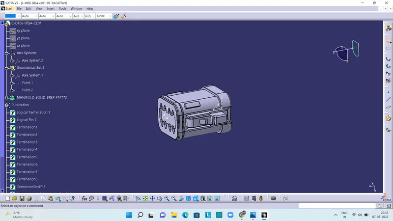
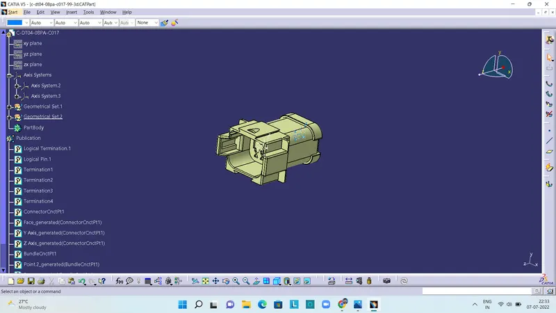
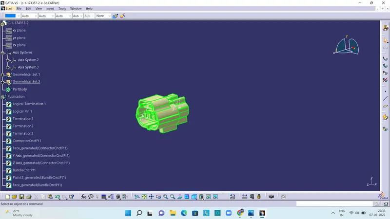
The above pictures are the various connectors that are defined as connectors and then connection points are made for connector and bundle, with the help of axis and points. Then these connectors are added into the created catalogue.
Harness-A Assembly
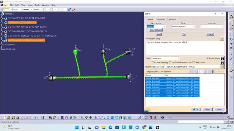
The above picture shows the Harness-A assembly and checking of bundle continuity of Harness-A using search command and the result shows that the bundles are continuous. After defining the connectors, branches (bundles) are created and finally assembly is created. These are all done in Electrical harness assembly workbench.
Harness-B Assembly
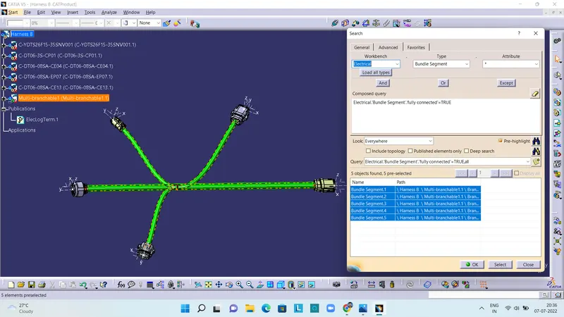
The above picture shows the Harness-B assemblychecking of bundle continuity of Harness-B using search command. It helps in identifying any discontinuities in the bundle. The result shows that the bundles are continuous. These are all done in Electrical harness assembly workbench.
Final Assembly
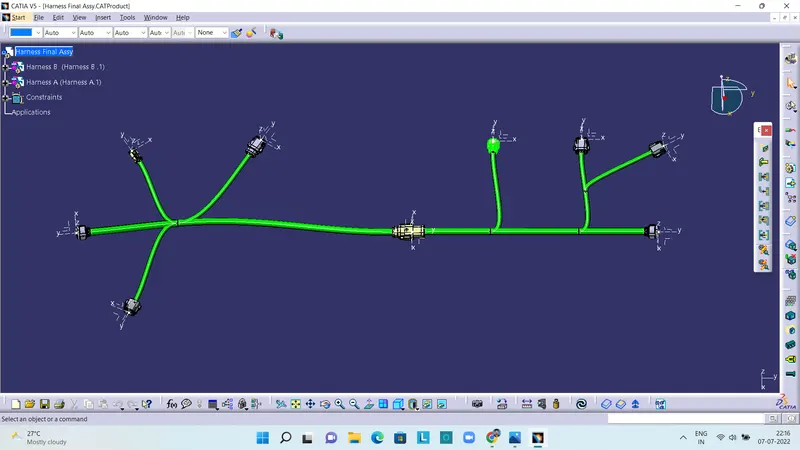
Then atlast the harness-A and harness-B are connected using connect electrical devices command in electrical assembly design workbench. And the harness assembly have been obtained.
The part files, assembly files (also in .igs format) and catalogue are attached as zip.