Wiring harness design in CATIA V5 - 3D modeling Week 4 Challenge
Wiring harness design in CATIA V5 - 3D Modelling Week 4 Challenge
Aim
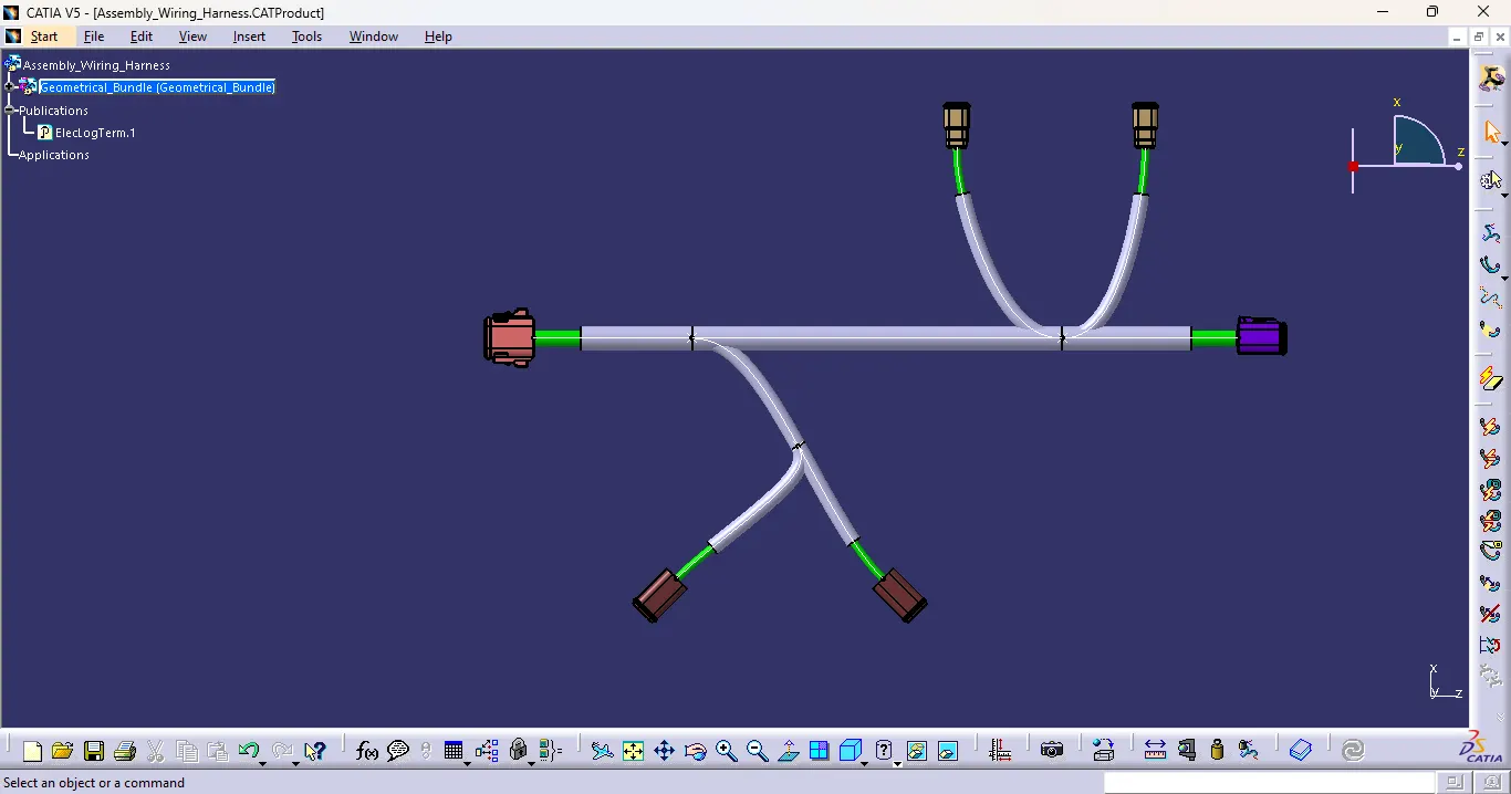
- Route the following harness layout in Electrical workbench. Make assumption for harness bundle diameters. Use Following connectors as shown in layout diagram.
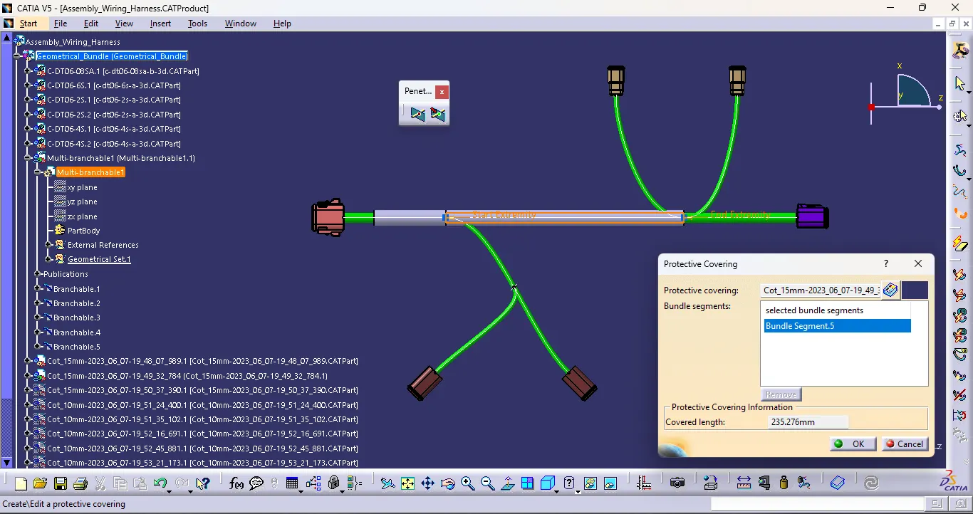
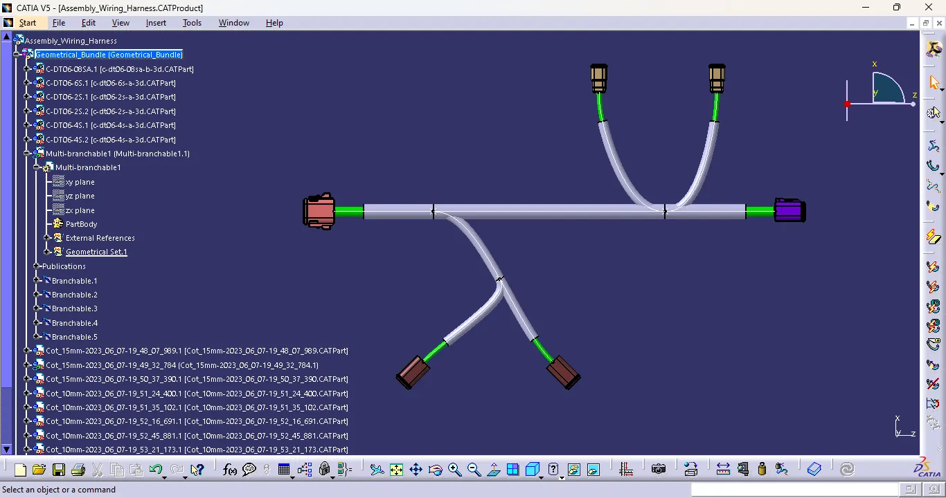
- Add protective covering on all branches connected to DT06-2S & DT06-4S connectors. Keep end extremity at 30mm (from connectors end).
Download connector 3D data from www.te.com
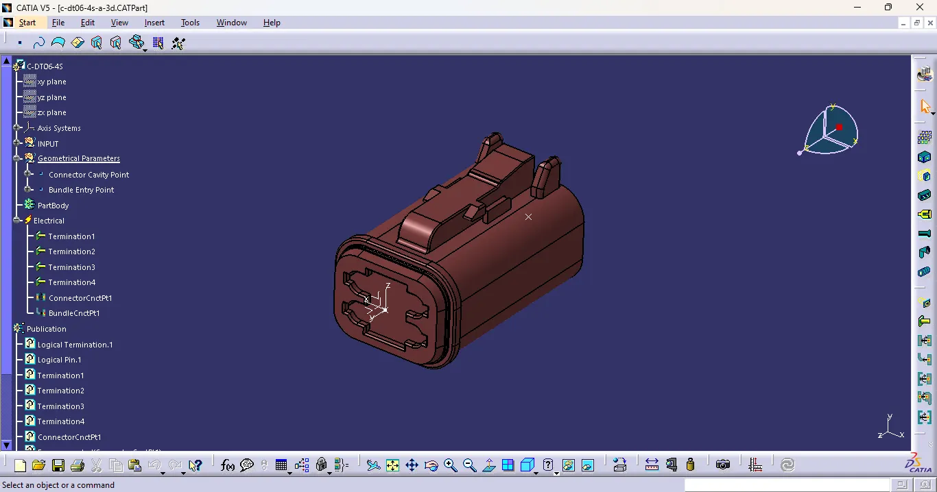
- DT06-4S
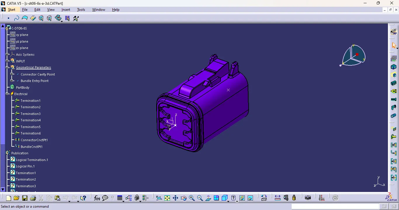
- DT06-6S
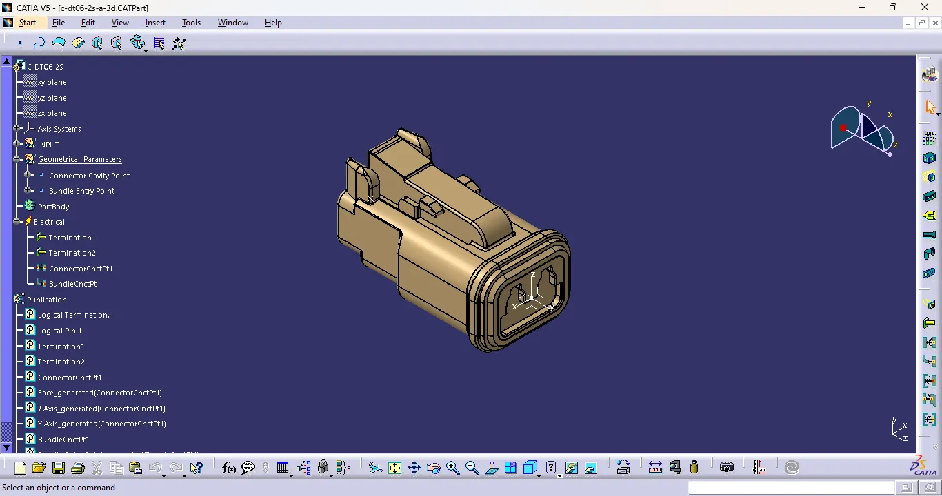
- DT06-2S
- DT06-08SA
Introduction
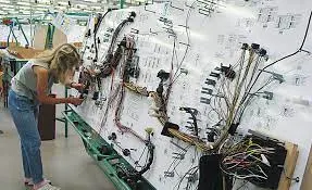
- Wiring Harness Routing
A wiring harness routing structure includes a wiring harness routing member configured to be attached to a vehicle body and a protector that accommodates and holds a wiring harness. The protector has a recess shape in which the protector is opened in one direction in a sectional view.
- Connectors
Connectors are the electro-mechanical devices used to form a continuous electronic signal to connect wire harnesses to a power source or circuit. On a basic level, connectors consist of male-ended plugs and female-ended jacks that can be joined together to relay an electronic signal.
- Protective Covering
Popular cable and wire harness coverings include: Heat shrink tubing—wraps snugly around wires and smooth out rough surfaces, providing thermal and electrical insulation. Adhesive-backed tubing provides a strong seal against moisture and chemicals that can corrode harness components.
Procedure
Step 1: Define the Mechanical Connectors Electrically.
- Creation of connector connection point and Connector Connection Axis.
- Make a midpoint on the contact face for wire bundle insertion.
- Create an axis system referencing the newly generated point and specifying the axis direction.
- The Y-Axis should be oriented towards the connector's front face.
- The X-Axis should be oriented towards the clip's locking mechanism.
- The Z-axis should be pointing across the connector from left to right.
- Creation of Bundle Connection Point.
- Define the part as a connector.
- Define connector connection point.
- Define Bundle connection point.
- DT06-4S
- DT06-6S
- DT06-2S
- DT06-08SA
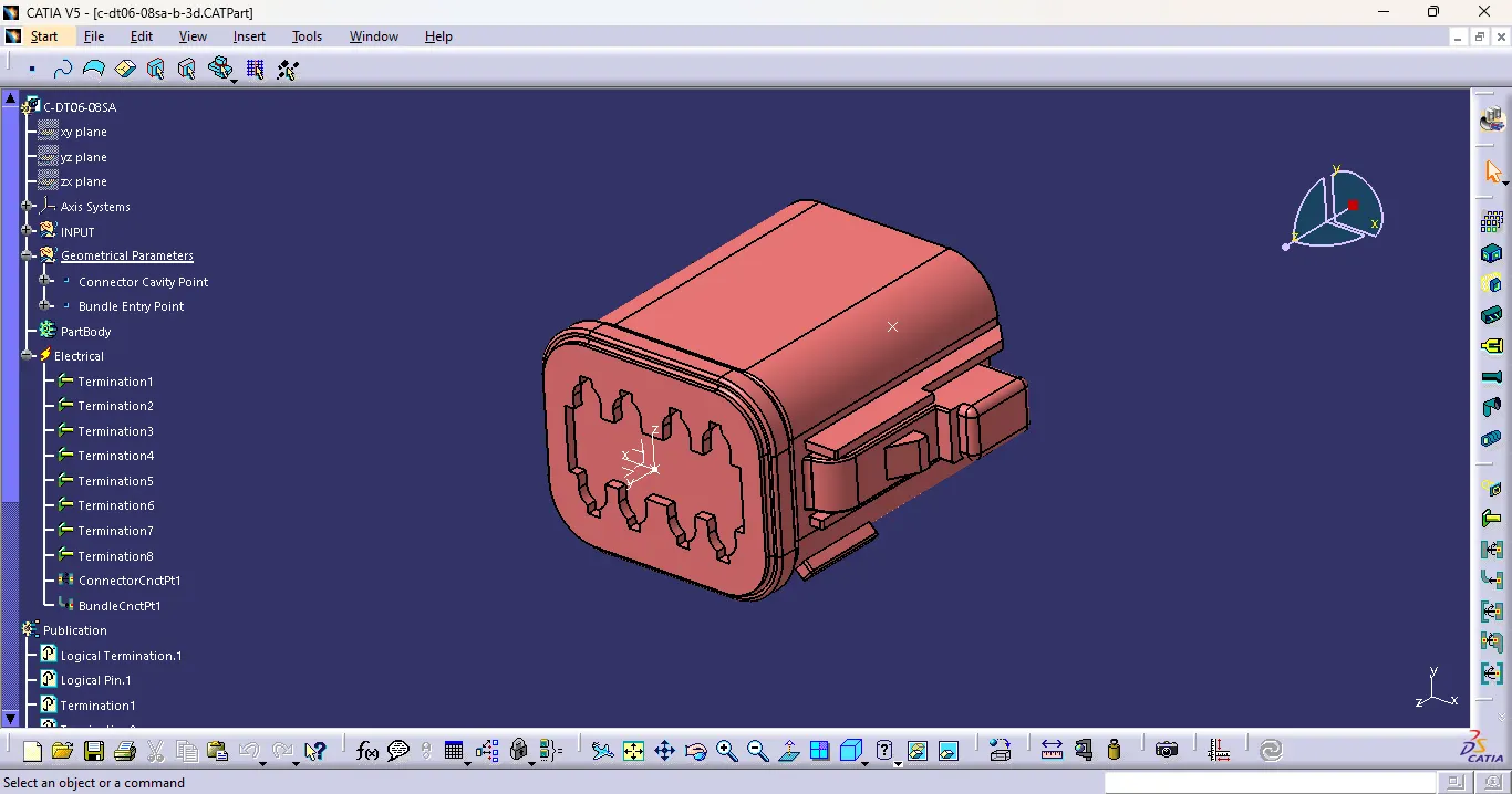
Step 2: Define Product File as Geometrical Bundle.
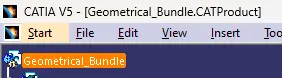
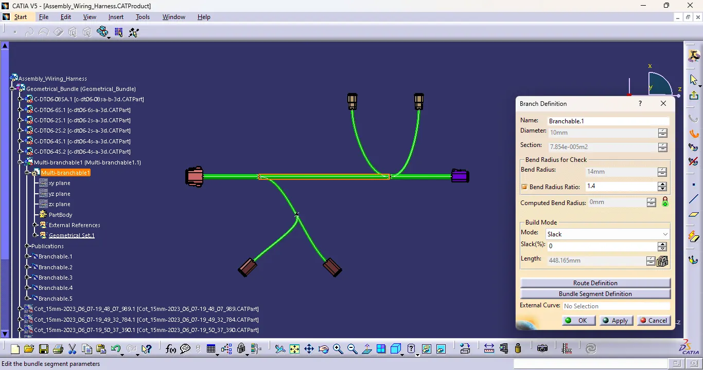
Step 3: Arranging the Connectors & Creating Multi-Branching to the connectors as per the design.
Branches diameters are 10mm and 5mm.
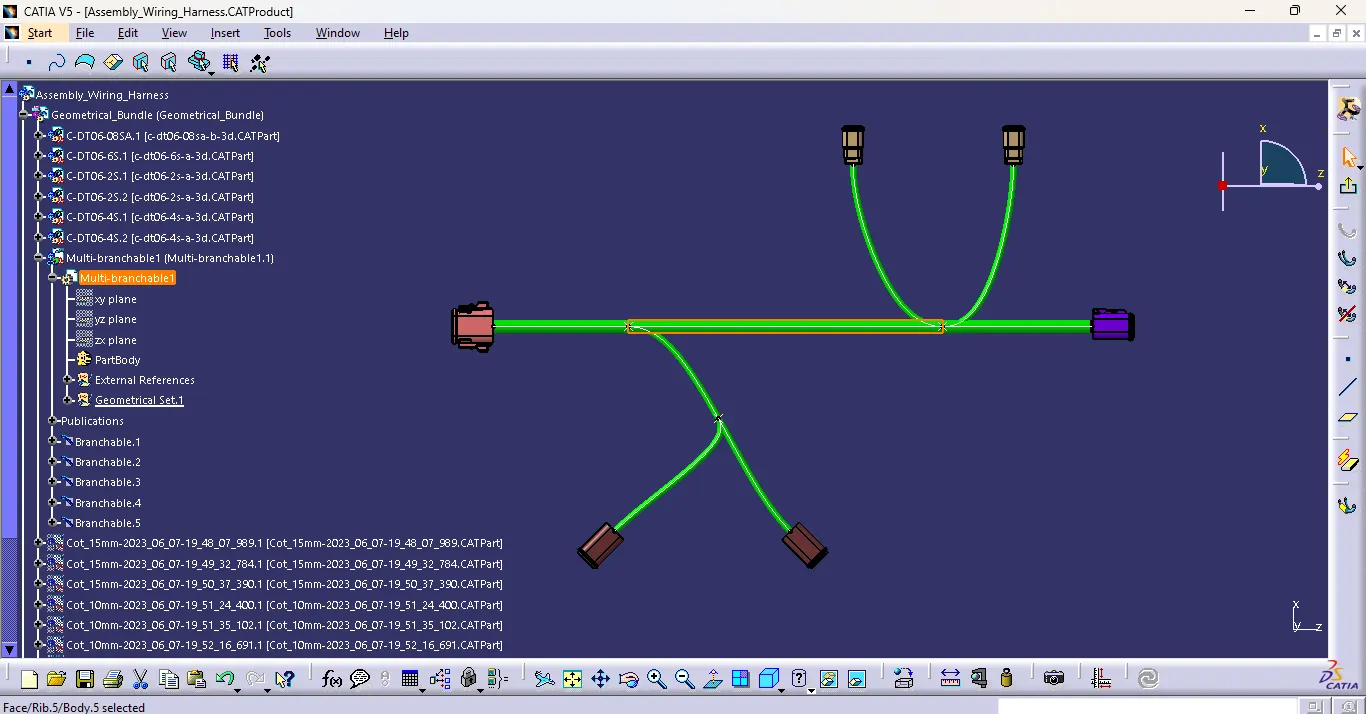
Step 4: Creation of Protective covering.
Create the protective covering with Cot tubes of 10mm and 15mm.
Provided End extrimity of 30mm From Connector ends.
Conclusion
Thus, the Wiring Harness Layout has been designed with the given inputs and the protective coverings also added on the required branches using Catia V5 Software.