Wiring harness design in CATIA V5 - 3D modeling Week 4 Challenge
Wiring harness design in CATIA V5
Week 4 Challenge 1
Objective:
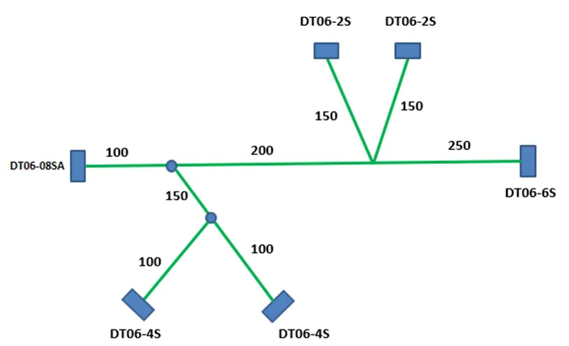
The objective of this report is to create a wiring harness layout in the Electrical Workbench, utilizing specified connectors and assuming suitable bundle diameters. Protective covering will be added to branches connected to DT06-2S & DT06-4S connectors, with a 30mm end extremity from the connector's end.
Design overview:
The design comprises four connectors: DT06-4S, DT06-6S, DT06-2S, and DT06-08SA, aligned as specified in the circuit diagram. To accommodate connectivity needs, branches were strategically integrated. Connecting wires were employed, with the thickest wire serving as the central wiring spine, while thinner wires formed branching circuits. Corrugated tubes, tailored to respective wire diameters, were implemented for safeguarding.
Design process:
The assembly process followed a top-down approach. A new electrical assembly file was created, named "geometric bundle," where components were added and defined electrically. Using the compass, components were positioned as per the circuit diagram. Shifting to the electrical harness assembly workbench, a multibranchable document was generated. This introduced a new CATPart file to the geometric bundle. Key parameters like name, build mode, diameter, and bend radius were defined. Notably, a bend radius of 1.4 to 1.5 times the bundle diameter was set for wires to ensure flexibility.
Transitioning to route definition, connectors were linked using bundle wires, activating routing commands. Selection of two bundle vectors facilitated connection between components. Individual connections were established through branch definition. To create multiple branches via an existing bundle, the multibranchable file was activated from the process tree. Branch points were added, originating from chosen parts of the bundle.
Exiting the routing workbench, protective covering was introduced. The geometric bundle assembly was enabled, and protective covering was activated. After selecting a suitable covering from the catalogue, it was applied to the designated bundle section. It was ensured that an adequate gap existed between the branch point and the covering's end point. This systematic process ensured efficient assembly and protective measures in line with the design's objectives.
Component specifications:
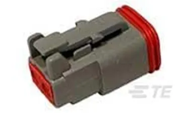
1 DT06-2S:
The DT06-2S connector is a rectangular-shaped housing designed for female terminals, forming a wire-to-wire connection system. It features a built-in primary locking mechanism within the housing and is sealable, ensuring secure and protected connections. This connector type is not a hybrid and is designed specifically for terminating wires and cables, making it a reliable choice for maintaining electrical connections in various applications.
|
Column1 |
Column2 |
|
Dimensions |
|
|
Compatible Insulation Diameter Range |
1.35 – 3.05 mm |
|
Product Length |
31.2 mm |
|
Product Width |
16.48 mm |
|
Connector Height |
15.77 mm |
|
Electrical Characteristics |
|
|
Operating Voltage (VAC) |
250 |
|
Operating Voltage (VDC) |
250 |
|
Nominal Voltage Architecture (V) |
12, 24, 48 |
|
Body Features |
|
|
Cable Exit Angle |
180° |
|
Contact Features |
|
|
Contact Type |
Socket |
|
Contact Size |
Size 16 |
|
Mating Pin Diameter |
1.59 mm |
|
Contact Current Rating (Max) (A) |
13 |
|
Mechanical Attachment |
|
|
Mating Alignment |
With |
|
Mating Alignment Type |
Polarized |
|
Strain Relief |
Add By Accessory |
|
Connector Mounting Type |
Cable Mount (Free-Hanging) |
|
Terminal Position Assurance |
Yes |
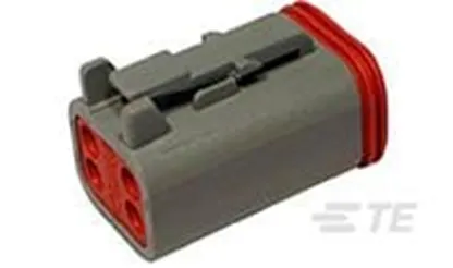
2 DT06-4S:
The DT06-4S connector features a housing designed specifically for female terminals and operates within a wire-to-wire connector system. With a mating pin diameter of 1.59 mm (0.063 inches), it offers reliable connections. This connector is designed for 4 positions and is suitable for power and signal circuit applications. Its ability to accommodate both power and signal transmission makes it versatile for various operational scenarios.
|
Feature |
Value |
|
Connector Shape |
Rectangular |
|
Connector & Housing Type |
Housing for Female Terminals |
|
Connector System |
Wire-to-Wire |
|
Sealable |
Yes |
|
Hybrid Connector |
No |
|
Primary Locking Feature |
Integrated in Housing |
|
Connector & Contact Terminates To |
Wire & Cable |
|
Configuration Features: |
|
|
Feature |
Value |
|
Number of Positions |
4 |
|
Number of Rows |
2 |
|
Blank Cavity Position |
0 |
|
Electrical Characteristics: |
|
|
Feature |
Value |
|
Operating Voltage (VAC) |
250 |
|
Operating Voltage (VDC) |
250 |
|
Nominal Voltage Architecture (V) |
12, 24, 48 |
|
Body Features: |
|
|
Feature |
Value |
|
Cable Exit Angle |
180° |
|
Contact Features: |
|
|
Feature |
Value |
|
Contact Type |
Socket |
|
Contact Size |
Size 16 |
|
Mating Pin Diameter |
1.59 mm [0.063 in] |
|
Contact Current Rating (Max) (A) |
13 |
|
Mechanical Attachment: |
|
|
Feature |
Value |
|
Mating Alignment |
With |
|
Mating Alignment Type |
Polarized |
|
Strain Relief |
Add By Accessory |
|
Connector Mounting Type |
Cable Mount (Free-Hanging) |
|
Terminal Position Assurance |
Yes |
|
Housing Features: |
|
|
Feature |
Value |
|
Housing Material |
PA GF |
|
Centerline (Pitch) |
4.45 mm [0.175 in] |
|
Dimensions: |
|
|
Feature |
Value |
|
Compatible Insulation Diameter Range |
2.23 – 3.68 mm |
|
Row-to-Row Spacing |
9.12 mm |
|
Product Length |
30.94 mm |
|
Product Width |
18.19 mm |
|
Connector Height |
18.39 mm |
|
Usage Conditions: |
|
|
Feature |
Value |
|
Operating Temperature (Max) |
125 °C [257 °F] |
|
Operating Temperature Range |
-55 – 125 °C [-67 – 257 °F] |
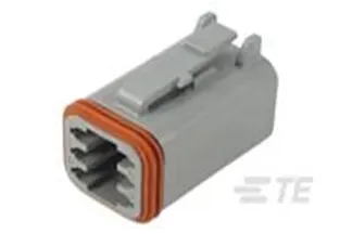
3 DT06-6S
The DT06-4S connector is designed as a housing for female terminals, facilitating secure connections. It features a mating pin diameter of 1.59 mm (0.063 inches) and operates within a wire-to-wire connector system. With a configuration of 6 positions, it allows for multiple connections. The centreline pitch is set at 9.12 mm (0.359 inches), providing a consistent spacing for efficient wiring.
|
Product Type |
Column1 |
|
Feature |
Value |
|
Connector Shape |
Rectangular |
|
Connector & Housing Type |
Housing for Female Terminals |
|
Connector System |
Wire-to-Wire |
|
Sealable |
Yes |
|
Hybrid Connector |
No |
|
Primary Locking Feature |
Integrated in Housing |
|
Connector & Contact Terminates To |
Wire & Cable |
|
Configuration Features: |
|
|
Feature |
Value |
|
Number of Positions |
6 |
|
Number of Rows |
2 |
|
Blank Cavity Position |
0 |
|
Electrical Characteristics: |
|
|
Feature |
Value |
|
Operating Voltage (VAC) |
250 |
|
Operating Voltage (VDC) |
250 |
|
Nominal Voltage Architecture (V) |
12, 24, 48 |
|
Body Features: |
|
|
Feature |
Value |
|
Cable Exit Angle |
180° |
|
Contact Features: |
|
|
Feature |
Value |
|
Contact Type |
Socket |
|
Contact Size |
Size 16 |
|
Mating Pin Diameter |
1.59 mm [0.063 in] |
|
Contact Current Rating (Max) (A) |
13 |
|
Mechanical Attachment: |
|
|
Feature |
Value |
|
Mating Alignment |
With |
|
Mating Alignment Type |
Polarized |
|
Strain Relief |
Add By Accessory |
|
Connector Mounting Type |
Cable Mount (Free-Hanging) |
|
Terminal Position Assurance |
Yes |
|
Housing Features: |
|
|
Feature |
Value |
|
Housing Material |
PA GF |
|
Centreline (Pitch) |
9.12 mm [0.359 in] |
|
Dimensions: |
|
|
Feature |
Value |
|
Compatible Insulation Diameter Range |
2.23 – 3.68 mm |
|
Row-to-Row Spacing |
4.45 mm [0.175 in] |
|
Product Length |
30.94 mm |
|
Product Width |
18.19 mm |
|
Connector Height |
22.63 mm |
|
Usage Conditions: |
|
|
Feature |
Value |
|
Operating Temperature (Max) |
125 °C [257 °F] |
|
Operating Temperature Range |
-55 – 125 °C [-67 – 257 °F] |
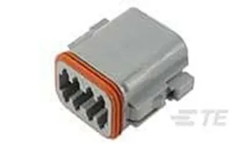
4 DT06-08SA
The DT06-08SA connector serves as a housing tailored for female terminals, facilitating robust connections. With a mating pin diameter of 1.59 mm (0.063 inches), it operates within a wire-to-wire connector system. With 8 positions, it offers versatility for multiple connections. The centreline pitch, set at 9.12 mm (0.359 inches), ensures consistent spacing, contributing to an efficient wiring arrangement.
|
Product Type Features: |
Column1 |
|
Feature |
Value |
|
Connector Shape |
Rectangular |
|
Connector & Housing Type |
Housing for Female Terminals |
|
Connector System |
Wire-to-Wire |
|
Sealable |
Yes |
|
Hybrid Connector |
No |
|
Primary Locking Feature |
Integrated in Housing |
|
Connector & Contact Terminates To |
Wire & Cable |
|
Electrical Characteristics: |
|
|
Feature |
Value |
|
Operating Voltage (VAC) |
250 |
|
Operating Voltage (VDC) |
250 |
|
Nominal Voltage Architecture (V) |
12, 24, 48 |
|
Body Features: |
|
|
Feature |
Value |
|
Cable Exit Angle |
180° |
|
Connector & Keying Code |
A |
|
Dimensions: |
|
|
Feature |
Value |
|
Compatible Insulation Diameter Range |
2.23 – 3.68 mm |
|
Row-to-Row Spacing |
4.45 mm [0.175 in] |
|
Product Length |
30.91 mm |
|
Product Width |
19.71 mm |
|
Connector Height |
37.21 mm |
|
Usage Conditions: |
|
|
Feature |
Value |
|
Operating Temperature (Max) |
125 °C [257 °F] |
|
Operating Temperature Range |
-55 – 125 °C [-67 – 257 °F] |
|
Product Type Features: |
|
|
Feature |
Value |
|
Connector Shape |
Rectangular |
|
Connector & Housing Type |
Housing for Female Terminals |
|
Connector System |
Wire-to-Wire |
|
Sealable |
Yes |
|
Hybrid Connector |
No |
|
Primary Locking Feature |
Integrated in Housing |
|
Connector & Contact Terminates To |
Wire & Cable |
|
Electrical Characteristics: |
|
|
Feature |
Value |
|
Operating Voltage (VAC) |
250 |
|
Operating Voltage (VDC) |
250 |
|
Nominal Voltage Architecture (V) |
12, 24, 48 |
|
Body Features: |
|
|
Feature |
Value |
|
Cable Exit Angle |
180° |
|
Connector & Keying Code |
A |
|
Dimensions: |
|
|
Feature |
Value |
|
Compatible Insulation Diameter Range |
2.23 – 3.68 mm |
|
Row-to-Row Spacing |
4.45 mm [0.175 in] |
|
Product Length |
30.91 mm |
|
Product Width |
19.71 mm |
|
Connector Height |
37.21 mm |
|
Usage Conditions: |
|
|
Feature |
Value |
|
Operating Temperature (Max) |
125 °C [257 °F] |
|
Operating Temperature Range |
-55 – 125 °C [-67 – 257 °F] |
Routing and Assembly:
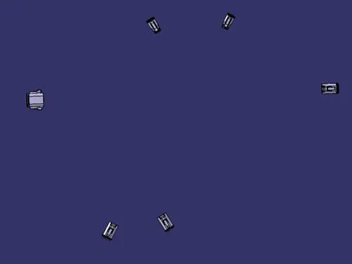
The arrangement of components closely follows the circuit diagram's depiction. Each component has been strategically oriented to optimize connectivity and functionality. Notably, the bundle points of the components are aligned along the central spine, creating a streamlined pathway for the main bundle. This arrangement enhances the harness's structural integrity and minimizes tangling. Furthermore, the connectors' connection points for the remaining components are positioned radially outward, ensuring efficient and accessible connections while facilitating clear pathways for routing. This layout not only adheres to the original circuit diagram but also considers practical considerations for ease of assembly and future maintenance.
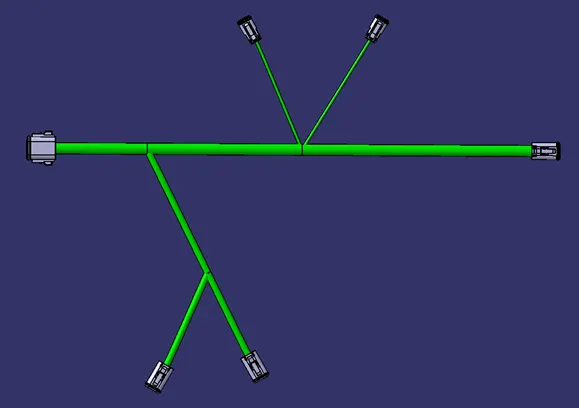
During the routing phase, the harness incorporates three wire diameters for optimum connectivity. The 13 mm diameter spine links DT06-6S to DT06-08SA connectors. Wires connected to DT06-4S feature a 7 mm diameter, while those linked to DT06-2S are 3 mm in diameter. These wires commence and terminate at bundle connection points. Branches are established at designated intervals, aligning with the circuit diagram. Protective corrugated tubes, 15 mm, 10 mm, and 5 mm in diameter, sourced from “COT_tubes” catalogue, encase the wires with a 30 mm gap between them. Junctions maintain nominal spacing for comprehensive protection.
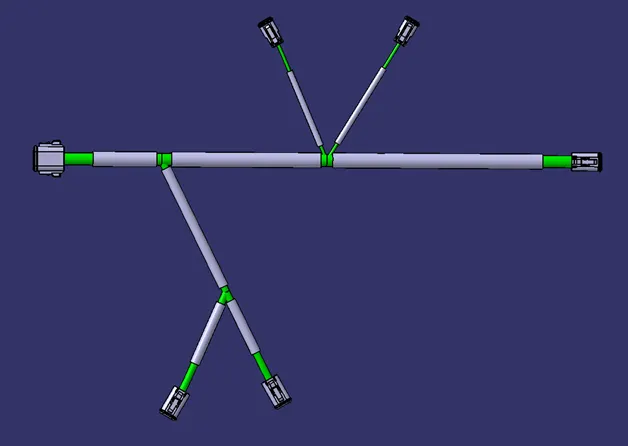
Protective covering:
<!-- [if !supportLists]-->1. <!--[endif]-->Tube Creation: In the electrical part workbench, create a new part file. Define it as a protection part, specifying type, inner diameter, thickness, and bend radius (1.5 times the outer radius). Add resulting parts to the COT_tubes catalogue.
<!-- [if !supportLists]-->2. <!--[endif]-->Import and Placement: In the assembly, import the required COT tube to the wire. Activate protective covering in the geometric bundle assembly.
<!-- [if !supportLists]-->3. <!--[endif]-->Application: Select the wire branch for COT tube application. Double-click and adjust covering's end extremities as guided.
Conclusion:
In the culmination of this report, the intricacies of a fundamental wiring harness assembly have been meticulously explored. The assembly layout adeptly positions components, with connectors DT06-2S, DT06-4S, DT06-6S, and DT06-08SA as main components. Notably, bundle points aligned along the spine optimize connectivity, while outward-facing connectors facilitate efficient radial connections. Routing incorporated wires of varying diameters, each protected by corrugated tubes (COT tubes).