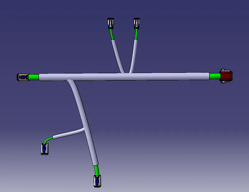
Wiring harness design in CATIA V5 - 3D modeling Week 4 Challenge
Objective :
To define the Mechanical connectors electrcally and store it in the Catalogue and Prepare the bundle routing for the connectors and orient the bundle in a given harness.
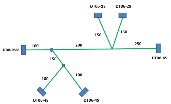
Given data :
Preparation of Wiring harness assembly:
Wiring Harness assembly product contains of mainly three components, they are:
- Harness Context Assembly.
- Geometrical Bundle.
- Electrical Bundle.
Harness Context Assembly: This is the log level File that contains the harness geometrical bundle and assembly and the wire harness electrical bundle.
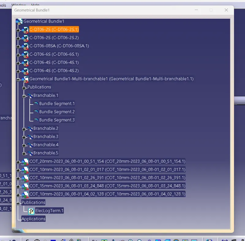
Geometrical Bundel: it is the main assembly which contains.
- Assembled part files.
- Multi-branch able (It contains all the wiring bundles)
- Clips and clamps.
- Connector and terminals.
Electrical bundle: It is the sub-level file which contains all the electrical circuit information.
Assembly operations:
As we all know, all the components are at 0,0,0 co-ordinates as default. We have place them at correct position within the geometrical bundle.
For that these tools are used as follows:
- Manipulator option – this option can be found in general assembly product file; it is tool used with simple drag and place respective to axis system.
- Translation and rotation – it’s also can be found in general assembly product file; it is used with help of values or dimensions respective to co-ordinates.
- Snap - it’s also can be found in general assembly product file; we can use it base on constrain like face, edge, surface, point, line etc.
- Smart move – its is advance option of snap, where a small window will appear on bottom right corner where we can easily access the part and select the desired face or edge etc.
- Compass – We can find this tool on top right corner of the window; we can use it by simply placing the compass on desired component and drag and drop the component at required position.
- Connecting Electrical Components – this tool only found in the Electrical Harness assembly, to use the tool first we must define the component as electrical component.
Wire Harness Routing:
There are 2 steps or parts involved in wire harness routing:
- Creation of simple wire harness bundle.
- Creation of multiple branches.
Before creating wire harness routing, we must met the requirements, that are:
- Geometrical bundle must be completed.
- All the components are places at correct positions.
- All the components must be defined as electrical components.
- Background Geometrical data must be needed and assembled in a geometrical bundle assembly context.
- All the clip and clamps / channels must be at desired locations.
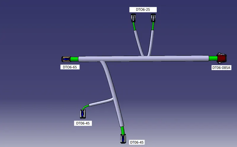
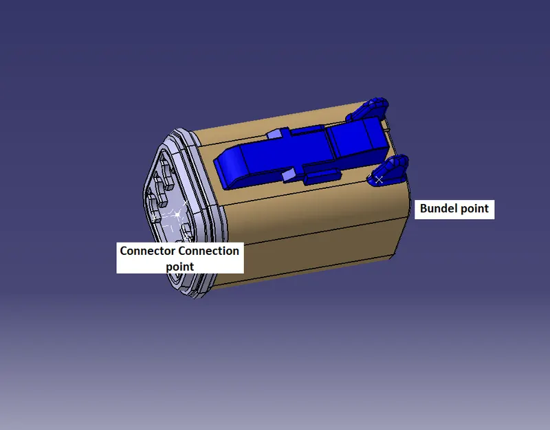
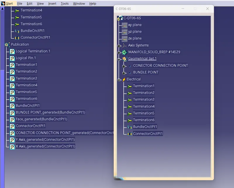
1. DTO6-6S :
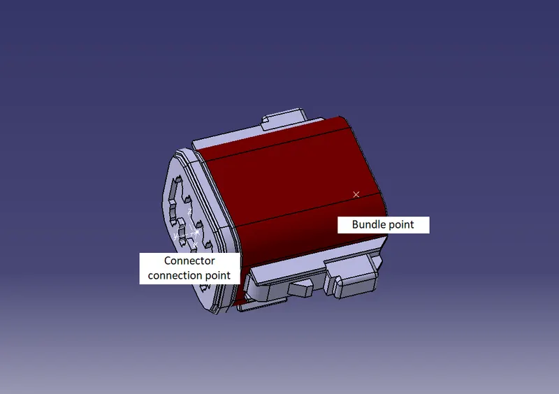
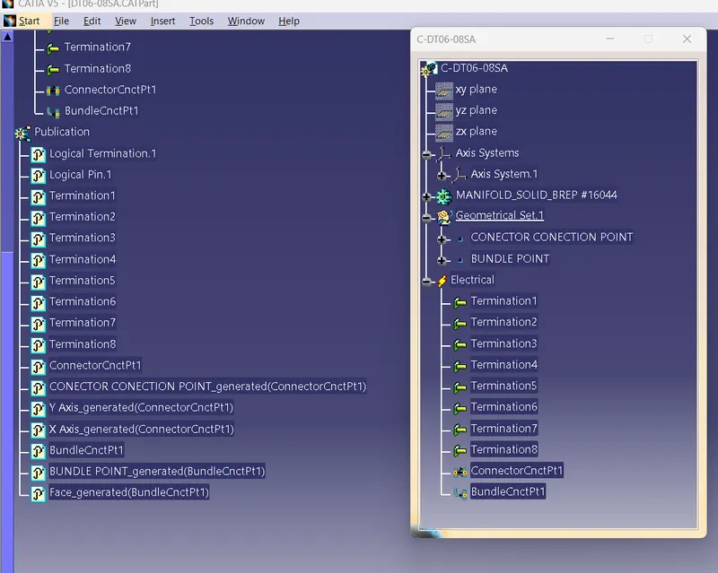
2. DT06-08SA
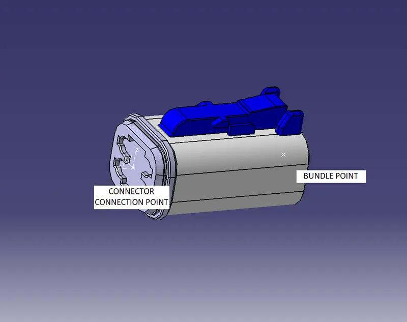
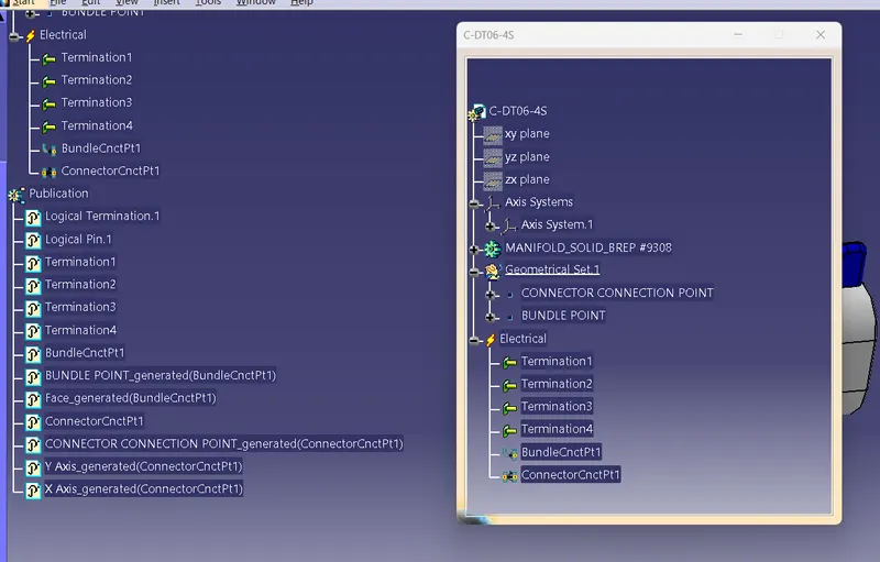
3. DT06-4S:
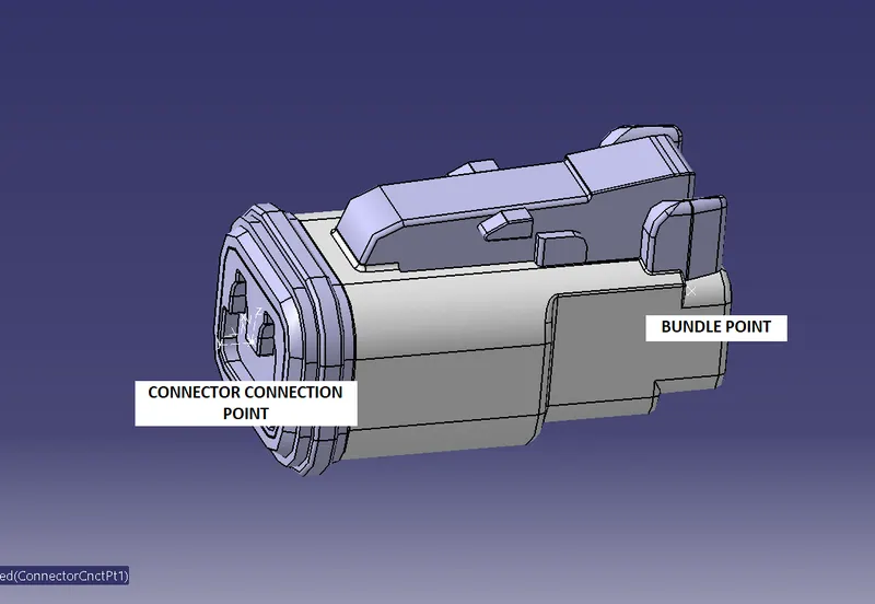
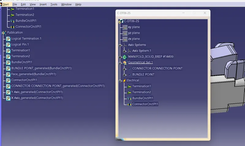
4. DT06-2S:
WIRING HARNESS ASSEMBLY: