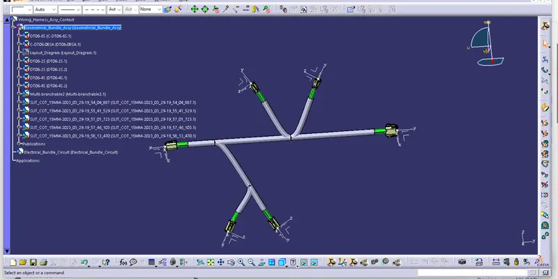
Wiring harness design in CATIA V5 - 3D modeling Week 4 Challenge
- PREPERATIN OF HARNESS ASSAMBLY:
First of all it is necessary to defined all our components electrically, now its time to prepare product assambly for given harness.
1. THE HARNESS CONEXT ASSAMBLY- This is the top level product file thal contains the Hrness Geometrical Bundle
2. GEOMETRICAL BUNDLE- This sub level product file is the wire harness product that contains all of the harness component ( clips, connector, support, groomets etc.) and actual physical bundle segments and branches.
3. ELECTRICAL BUNDLE- This sub level file contains all of the electrical circuit information.
- DEFINITING THE WIRING HARNESS ROUTING:
- Requiremnts for routing creation:
Geomerical bundle assambly is completed.
All components are placed at desired location.
All types of electrica connections are defined.
Background Geometry Data is available and assambled In Geometrical Bundle Context Assambly.
All clips, clamps, channels are placed at desired loction.
- DEFINING THE CONNECTORS ELECTRICALLY:
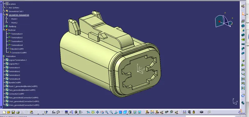
First of all we will defined the coonectors geometrically like Connector connection point, Connector connection axis and Connector bundle point. see image bwlow image
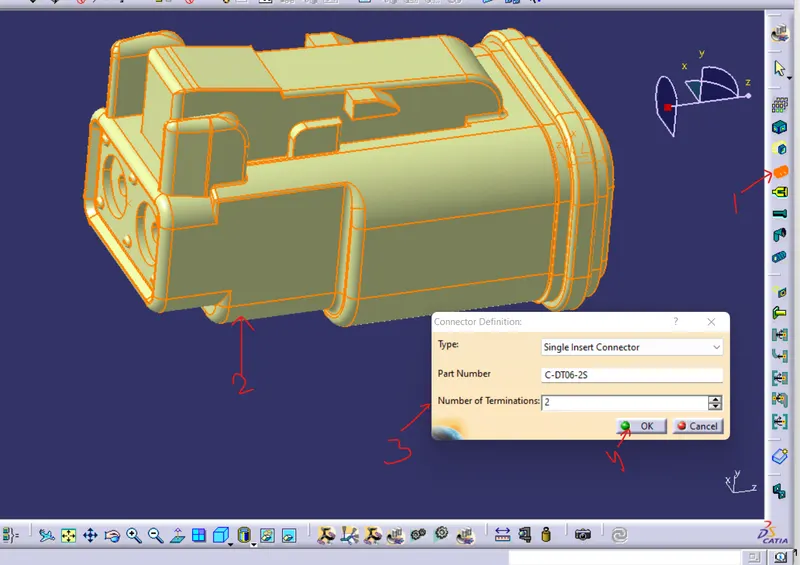
Now we will switch to ELECTRICAL PART DESIGN and Click on DEFINED CONNECTOR> CLICK ON PART>PROVIDE NO. OF ENTRY POINT > OK see below image
Now We will defined connector connection point go to CONNECTOR CONNECTION POIN>CLICK ON PART> select the proper requirement as shown in the figure below>click ok.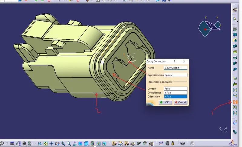
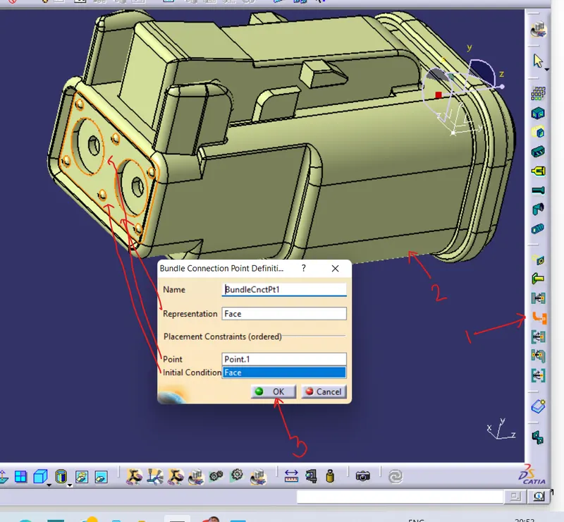
Now define=ing bundle entry point click on the go to DEFINE BUNDLE CONNECTION POINT>CLICK ON PART>select the proper asshown in below image >ok
Here our all parts are ELECTRICALLY DEFINED by following above process see below images
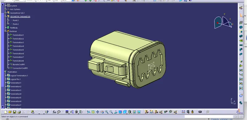
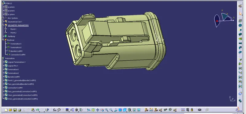
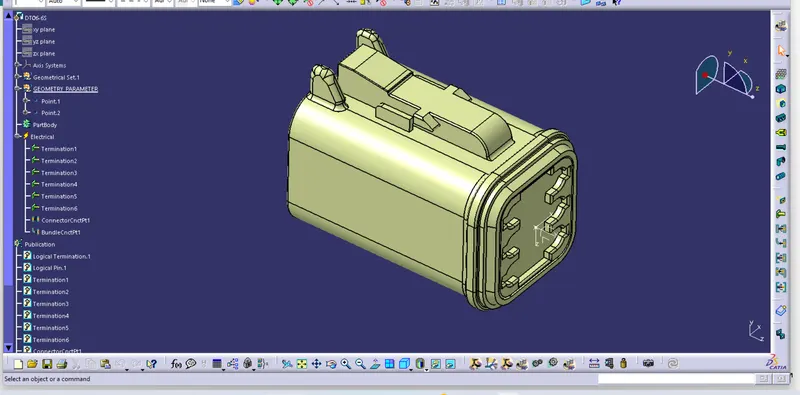
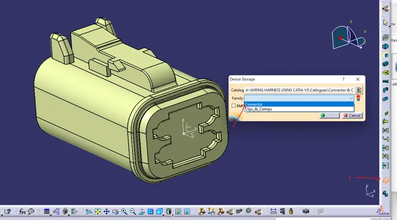
Now we wil add all this connector in Cataloge for this go to STORE DEVICE>SELECT FILE > select famaily as a connector as shown below>ok, similarly we will add all part in cataloge.
- WIRING HARNESS ASSAMBLY CREATION:
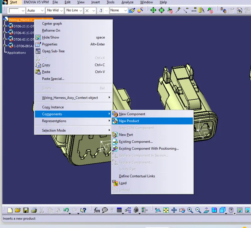
Firts we will create aproduct file named WIRING ARNESS ASSAMBLY CONTEXT>Right click on the produvt file >Component>New product. now open this product file and give name as Geometrical Bundle Assy and close >click on EXISIG Component and add all the necessary parts upon whuch we have to route th budle see below image
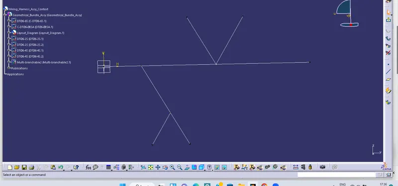
Now create the new Part file and create a sketch as required dimension given in challange and copy and paste in in the geometrical Bundle assy product file see below images
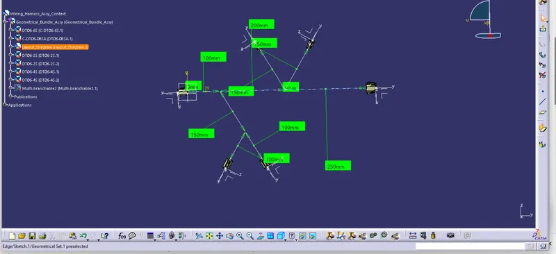
Now with the help of MOVE command available in the Assambly Design we will move our parts at its required place as given in the challanges , here the skecthes helps us to move our component at its defined place properly as shown in below image
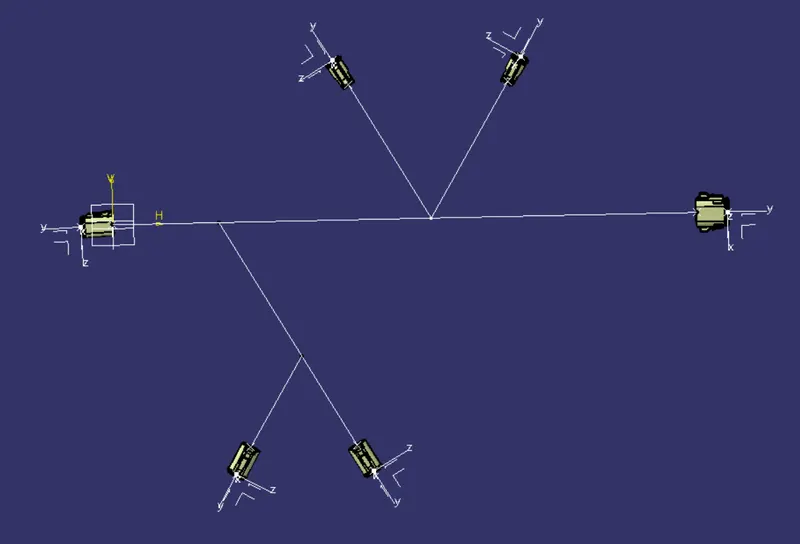
Now we will hide the sketch for easy selection in the part while Routing, Now we will switch to Electrical Harness Assambly and defined the Geometrical Bundle Assambly electrically , go to GEOMETRICAL BUNDLE COMMAND see image1 and click on the product Geometrical bundle assambly , after this the product file will be electrically defined.
Now go to MULTI BRANCHABLE DOCUMENT see below image2, here a popup window will be open as shown below image3
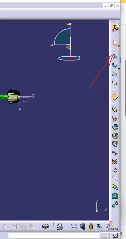
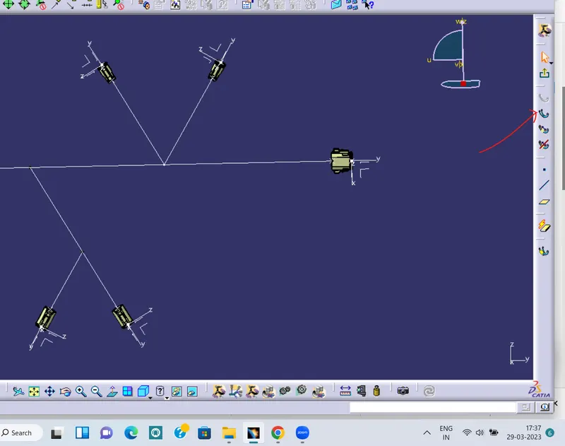
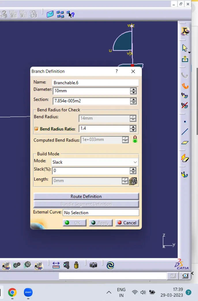
1 2 3
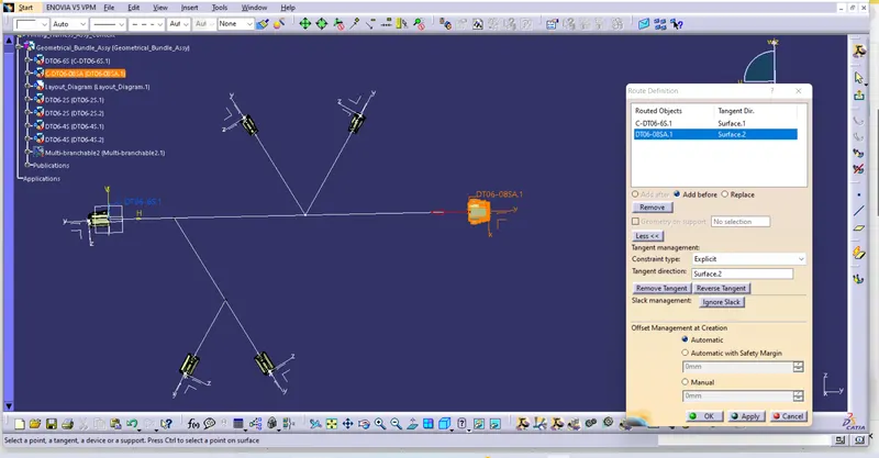
here we will give diameter(bundle diameter) and bend radius, the bend radius should be 1.4 to 1.5 times more than that of the diameter of the bundle , here we can also add slack percenatge (slack is nothing but increase in the lengt of the bundle between two parts ) Now click on the Route Definition>A popup window will be open shown in below image > Now select one connector bundle side and another connector bundle side properly for create bundle between them ensure that the direction of both the connector should be facing towards each other
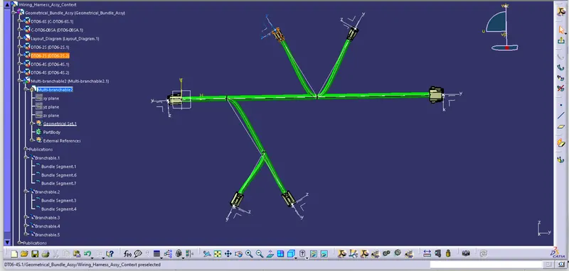
Now go to > Add Branch Point(for creating the branch bundle ) see image below image 1>click on budle>a popup window wiil be open > length give the length as required>ok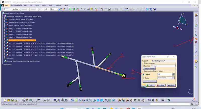
here our bundle will be devided in two pieces from which we can add branch bundle for routing
Now click on Branch deinition here all give the lesser diameter as the main bundle diametre click on ROUTE DEFINITION AND select the Branch point and connector bundle side.>ok>ok similarly do the same for all the connecctor
- ADDITION OF PROTECTIVE COVERING:
For adding Corrugated tubes go to PROTECTIVE COVERING>CLIC ON BUNDLE (below image1)>NOW browse the corrugated (see below image2) tube from the catalogu here always try to give coveting diameter greater than bundle diameter>ok
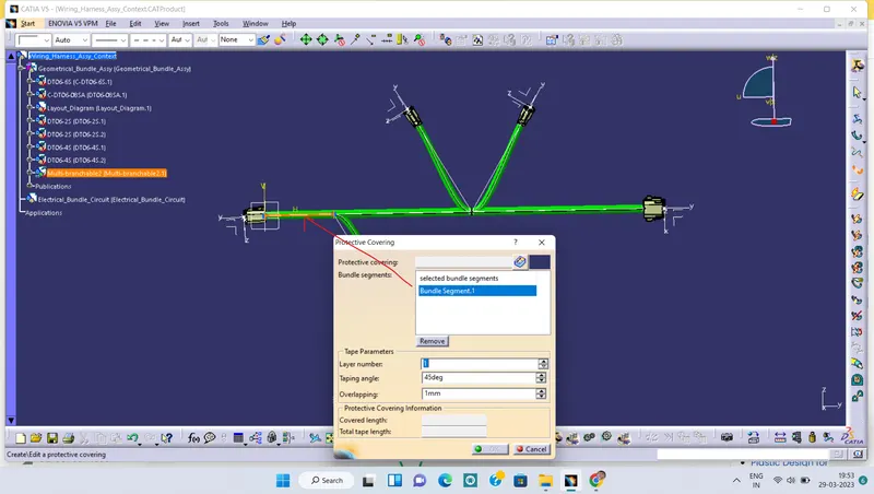
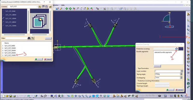
1 2
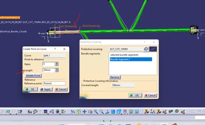
Now for maintaning 30 mm gap between the bundel and the corrugated tube double cliick on the start extrimity and give the length 30 mm as shown in below figure. Now we will repeate the same for the other corrrugated tubes .
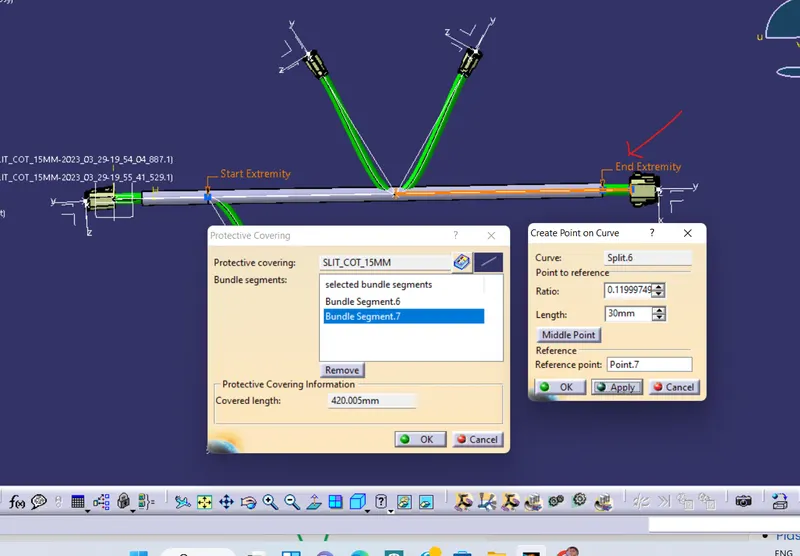
our final ROUTING WILL LOOK LIKE THIS