Wiring harness design in CATIA V5 - 3D modeling Week 4 Challenge
Electric Harness Assembly
What is Electric Harness Assembly in Catia?
Electric Harness Assembly in Catia is used for creating the bundle connection between the electric components. In this assembly the wire bundle is created between the electric connectors.
Before starting the assembly, it is always recommended to create the catalog of the electric component like connectors, mountings pins, etc., and the main things are wire covering, because this can only be access from the catalog.
Procedure for Electric Harness Assembly:
Frist all the electric components are need to be inserted in the assembly, either from catalog or manually.
- Go to Electric Harness Assembly, make sure to select correct module because Electric Harness Installation image looks same
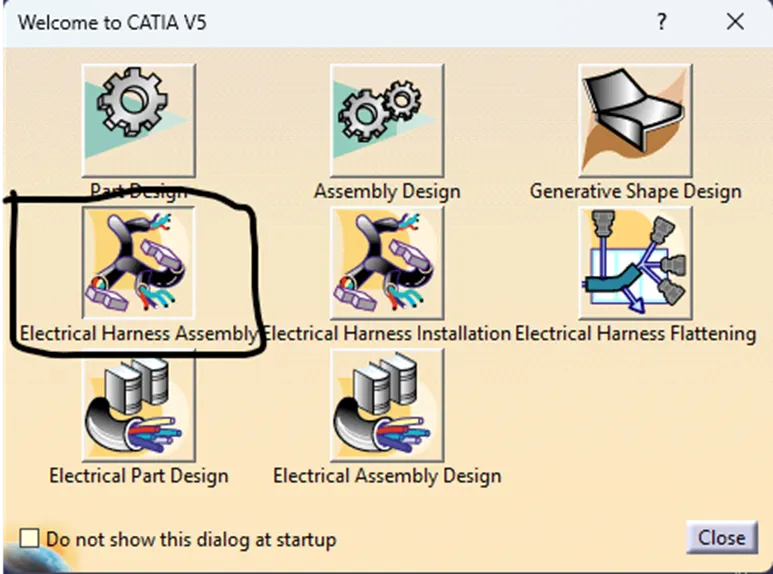 .
. - Select Geometric Bundle
 .
. - Click on the main product, so that we can create the geometric bundle
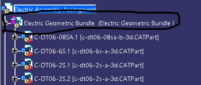 .
. - This will also change the symbol of the assembly from assembly design to Electric Assembly
- Select the geometric bundle
 .
. - It will take you to geometric bundle tab which looks like this

- Select branch definition to define the electric connection between the components
 .
. - This will open pop up window
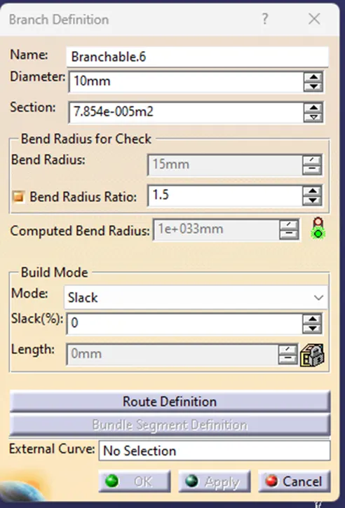 .
. - Here, we can define the wire parameter like diameter, bend radius (Normally more then 1) build mode.
- Click Route definition and this will open new window
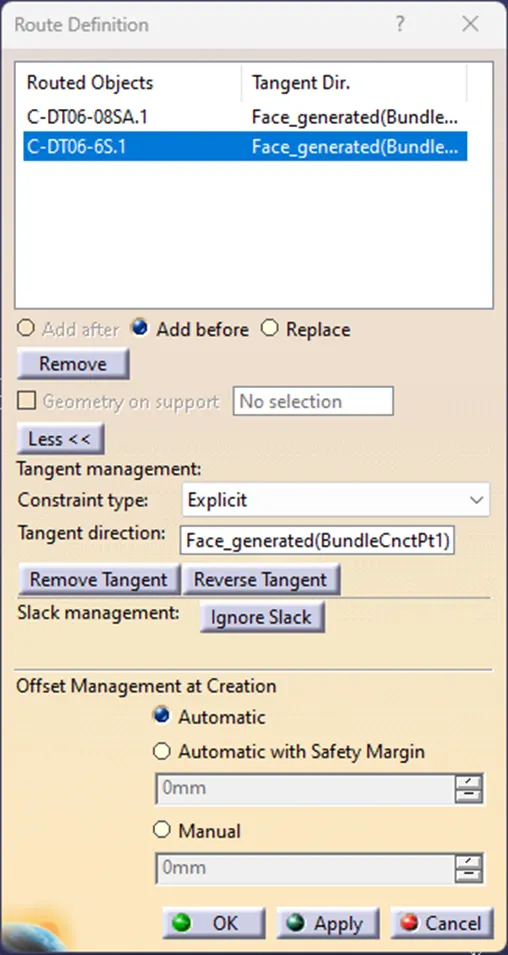 .
. - Here, we have to select the connector or the device between which connection are need to made. (Make sure parts are electric defined or else it will not be recognized)
- Here, we can change the parameter as per requirement and press OK.
- If we need to add the another branch in the Main Branch/Trunk, click on the Add Branch Point
 .
. - Select the branch where we need to put another branch. It will open dialog box
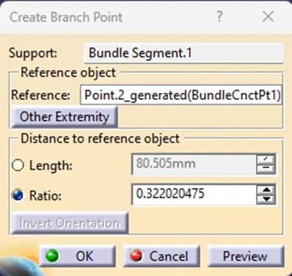
- Here, we can add branch based on length or the ratio of the full branch.
- After connecting all connectors and required equipment. We need to put covering on the wire for protection and also to give aesthetic look to wiring.
- Select Light Protective Covering
 .
. - It will open dialog box
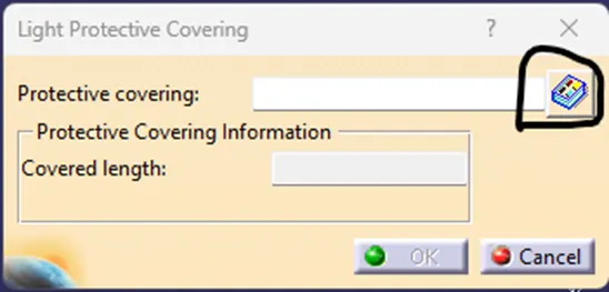
- Select the catalog and then select the covering with appropriate diameter.
- Select branch that need to be covered.
- The end extremities can be changed by double clicking the end extremities and press Ok.
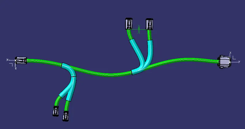
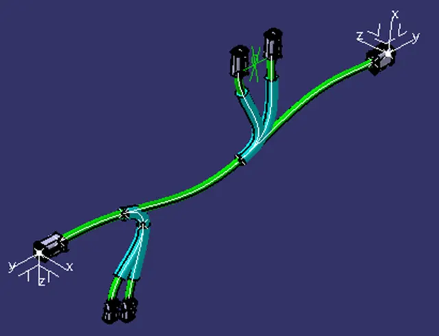
Geometric views and Structure Tree.
Front View
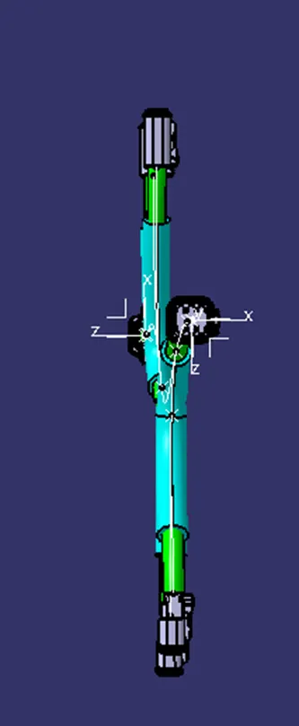
Side View
Isometric View
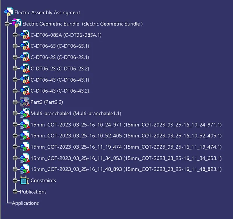
Structure Tree