Wiring harness design in CATIA V5 - 3D modeling Week 4 Challenge
AIM
Route the following harness layout in Electrical workbench. Make assumption for harness bundle diameters. Use Following connectors as shown in layout diagram.
Add protective covering on all branches connected to DT06-2S & DT06-4S connectors. Keep end extremity at 30mm (from connectors end)
CONNECTORS
- DT06-4S
- DT06-6S
- DT06-2S
- DT06-08SA
download the cad file of above mentioned connectors from www.te.com
Then open the cad file in catia part design workbench and create the connector connection point,connector connection axis system , bundle connection point .Switch to electrical part design and define it as a connector also define connector connection point and bundle connection point.
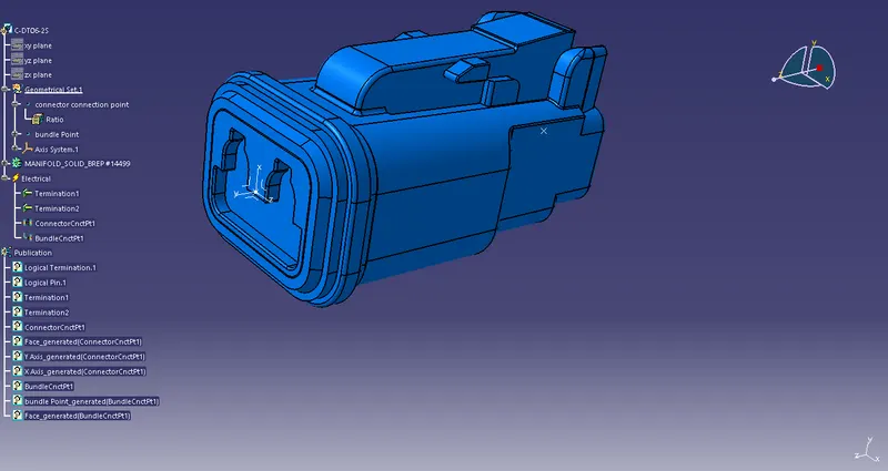
fig.1. Connector DT06-2S
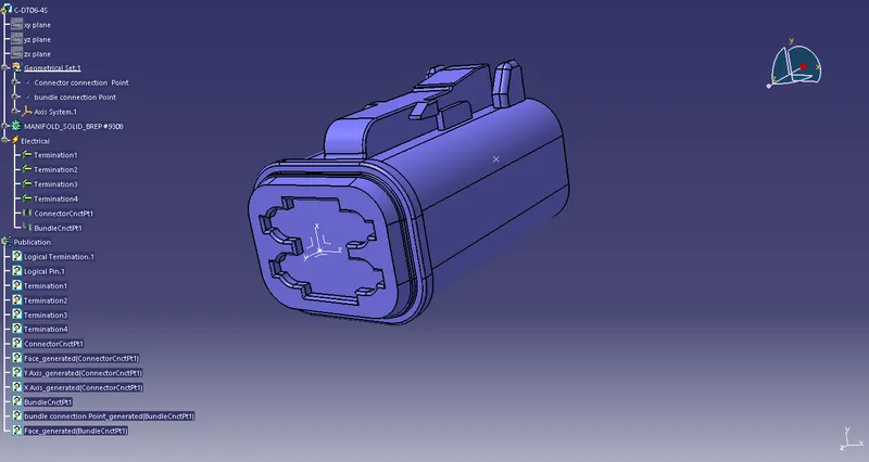
fig.2. Connector DT06-4S
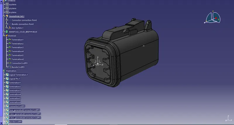
fig.3. Connector DT06-6S
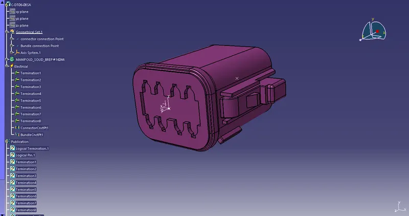
fig.4. Connector DT06-08SA
All the connectors defined as electrical connector and defined all the necessary properties to Connectors.
create a catalog document in connector family and store all the connector data in catalog document .
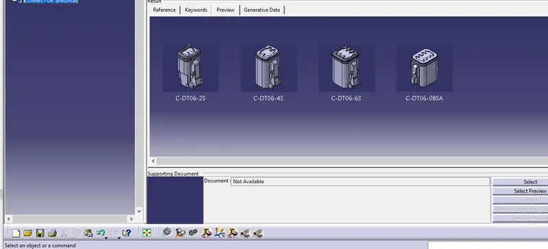
fig.4.Catalogdocument
Next create a new product in assembly workbench named as assembly wiring harness contex .it is the top level product file inside this product file created geometrical bundle and wire harness electrical bundle
Geometrical bundle contains all of the harness components i.e connectors ,clip, gromets and actual physical bundle segments and branches.
Above electricaly defined connectors add to geometrical bundle .Then switch to electrical harness assembly workbench and defined it as a electrical assembly by using the tool "Geometrical bundle".
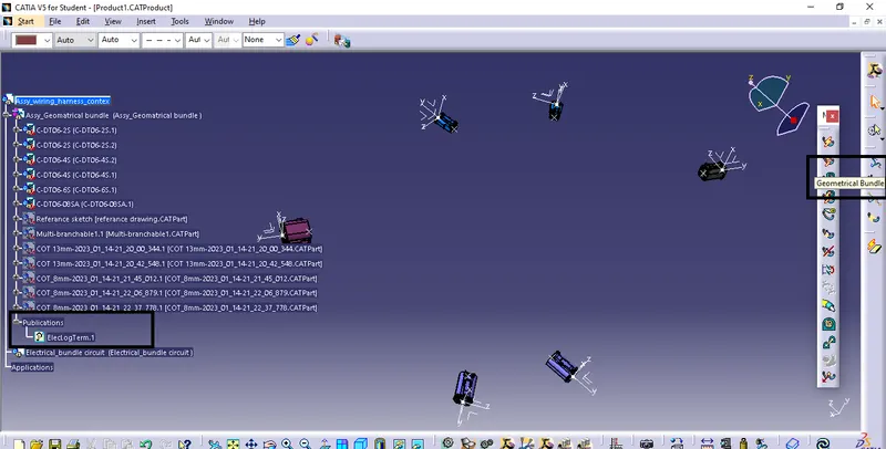
Fig.5. defined it as a electrical assembly by using the tool "Geometrical bundle"
To position the connectors , sketch created on the part design workbench by following the given data.
All the connectors positioed based on the reference sketch by using move options((manipulation,snap,smart move, using compass etc ) in the assembly workbench .
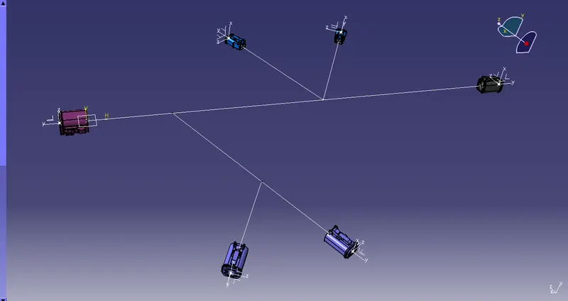
fig.6. All of the harness components placed at desired location
To create bundle segment in the geometrical bundle assembly use multi-branchable option in the electrical harness assembly workbench.
Multi-branchable catpart added to the geometrical bundle .it contains all the bundle segments and braches .first Select the diameter and bend ratio in the brach defenition window then use route defenition option and select the harness components to create the bundle .it automatically switch to electrical harness instalation workbench .
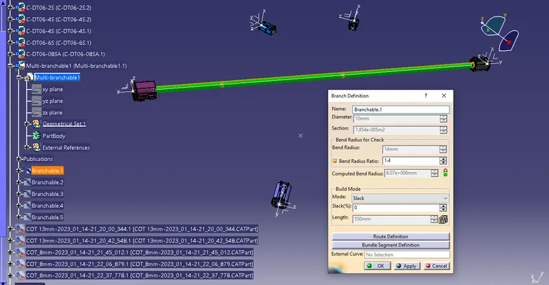
fig.7. Multi-branchable
here the main brach diameter is 10 mm and sub braches dia is 5 mm .For creating sub braches use "Add brach point" option in the electrical harness instalation workbench and select the bundle and provide required length where to create the new branch.
Add the branch point and harness component in the Route defenition option in side the branch defenition to create the sub branches.
After creating the bundles then switch to electrical harness assembly workbench and use protective covering option to add corugated tubes to the bundles.select the catalog document and use the proper cot tube and bundle segment to create the protective covering .Keep end extremity at 30mm (from connectors end).
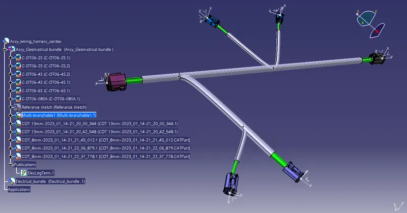
fig.8. routed harness layout