Wiring harness design in CATIA V5 - 3D modeling Week 4 Challenge
ELECTRICAL DISTRIBUTION SYSTEM(EDS):
EDS basicaly deals with physical and logical architecture,schematic development,power distribution,wiring harness design,wiring harness component design of given electrical system.
E & E ARCHITECTURE:
It is high level logical connectivity diagram represents the number of systems,subsystem and logical connectivity between them. it is also extended to show CAN(CONTROL AREA NETWORK) between different electronic controllers.
EDS:(ELECTRICAL DISTRIBUTION SYSTEM)
IT CONSIST OF 4 COMPONENTS
1. E&E ARCHITECTURE
2. LOGICAL SCHEMATIC
3. SCHEMATIC DEVELOPMENT
4. WH ROUTING AND PACKING
The term wiring harness refers to assembly of wires,connectors,terminals,protection covering,insulations,clips and clamps,fuse and relay boxes,retention devices,guiding channels,elctronic components
CONNECTORS:
Connectors are plastic molded housing with locking and retention features.
first import the CAD files in catia-V5
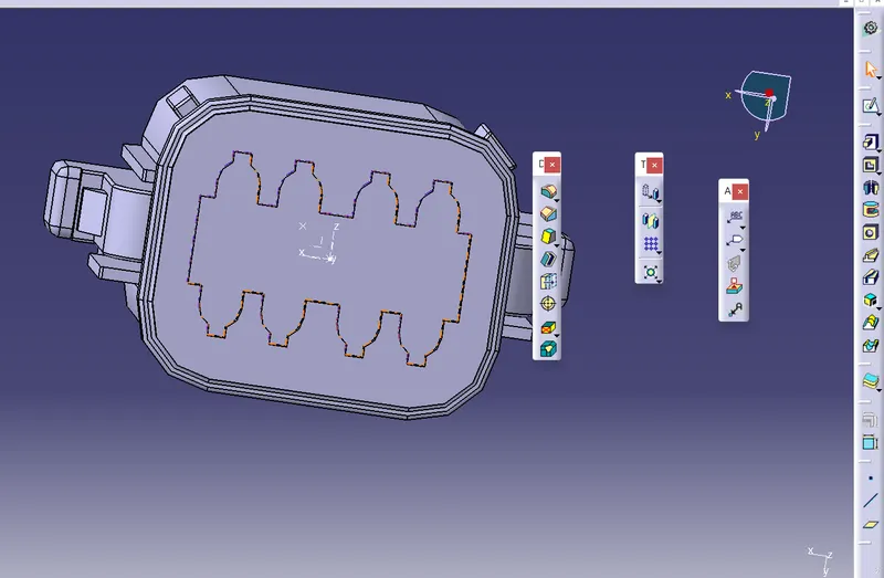
then start with part design and select point option to create midpoint
then create axis on the midpoint( Y axis should be facing the front face of connector
X axis should be pointing in the direction of lock
Z axis should be pointing across the connector from left to right)
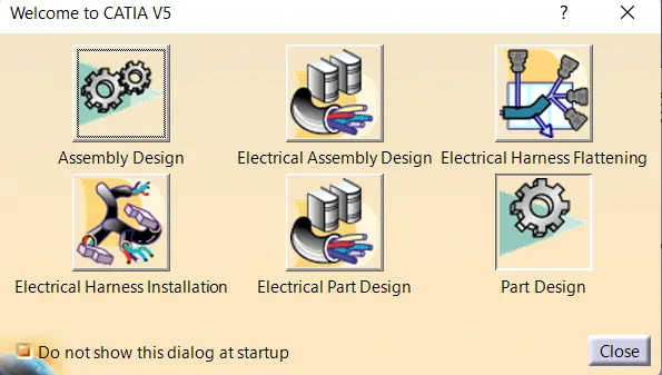
then select electrical part design
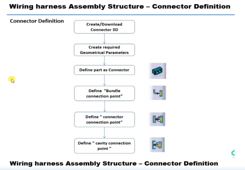
define the part as a connector by selecting it
also provide number of terminals
define bundle connection point
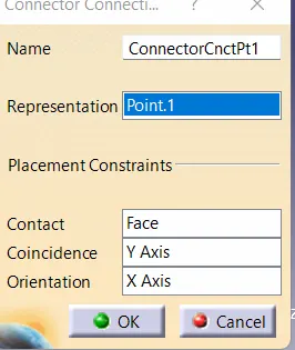
define connector connection point
NOW AFTER DEFINING GEOMETRICAL PARAMETERS FOR ALL THE CONNECTORS AND DEFINING THEM AS ELECTRICAL
NOW go to 'FILE' select new then product
New screen will pop up
now sketch the wiring part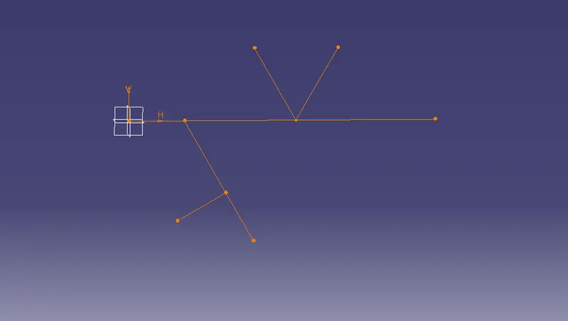
after sketching place connectors at desired loaction with the help of snap,manipulation or compass place the connectors at
desired location
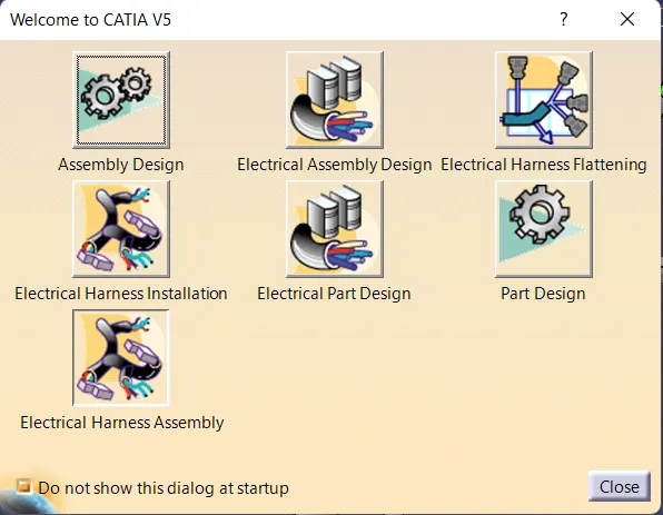
After that change to Electrical Harness Assembly
and select 1. which is Geometrical bundle
then click Multi-Branchable document
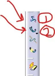
and select add branch
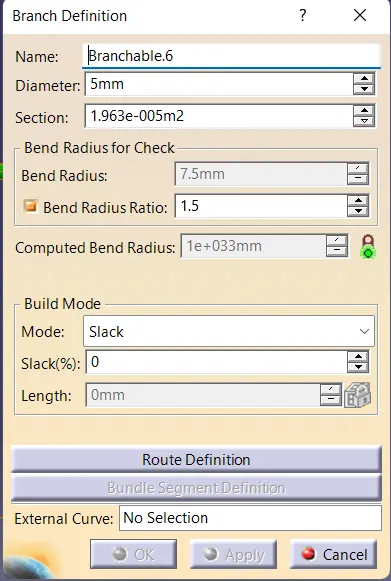
and define all the desired parameters and select route defination
and select the 2 objects between which you need harness
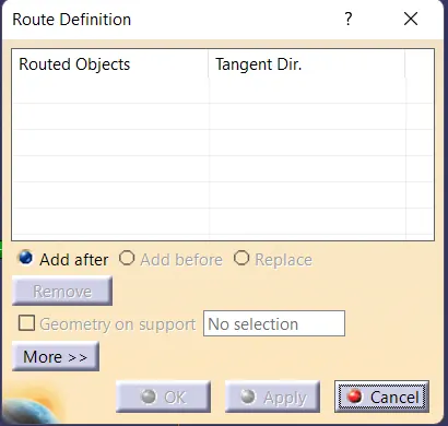
ADD 'Branch point' to give point at a desired location then sub branch
NOW TO APPLY PROTECTIVE COVERING
select 'PROTECTIVE COVERING BLOCK'
below MULTI-BRANCHABLE
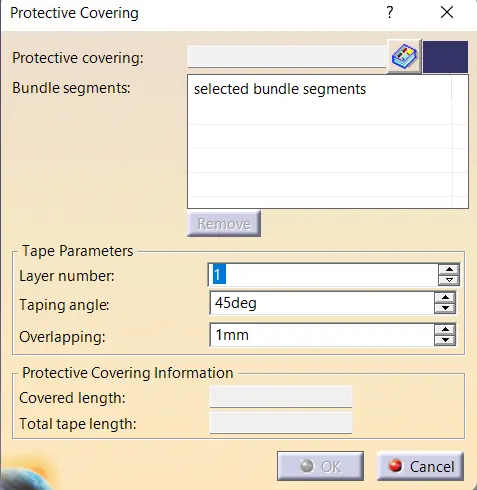
select segment
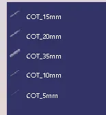
and select the desired COT (CORROGATED TUBE)
NOTE: COT tube should be greater then the diameter of harness
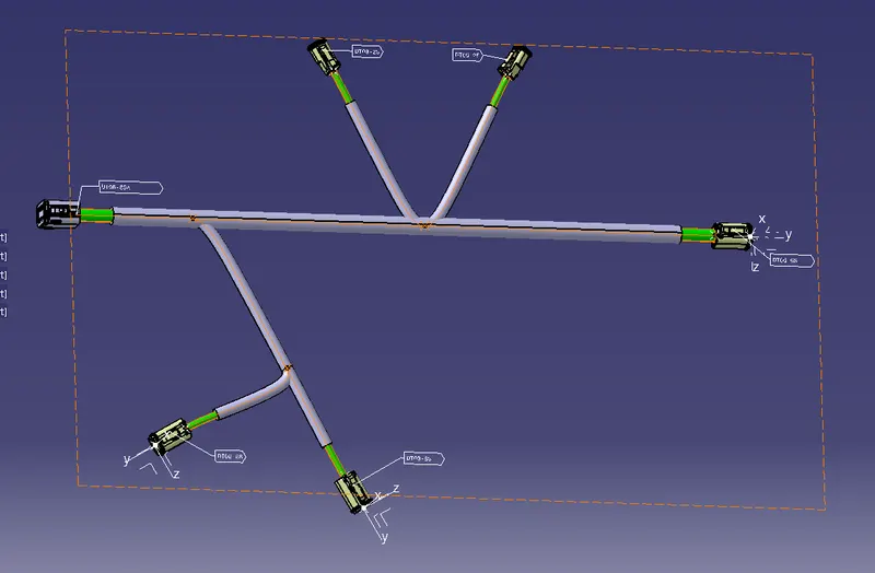
THE FILE NAME IS 'PRODUCT 1'