Wiring harness design in CATIA V5 - 3D modeling Week 4 Challenge
AIM: 1) To route the following harness layout in Electrical workbench.
2) To add protective covering on all branches connected to DT06-2S & DT06-4S connectors.
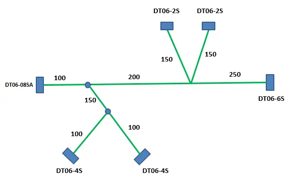
FIG 1
DT06-08SA, DT06-4S, DT06-4S,DT06-6S,DT06-2S are the connector components used in the harness.
Procedure:
1) The CAD data of the above mentioned connectors are downloaded and are geometrically and electrically defined in the Electrical Part design workbench in CATIA V5.
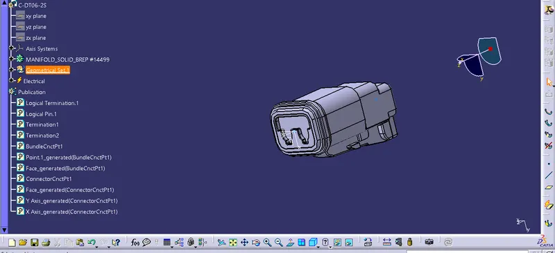
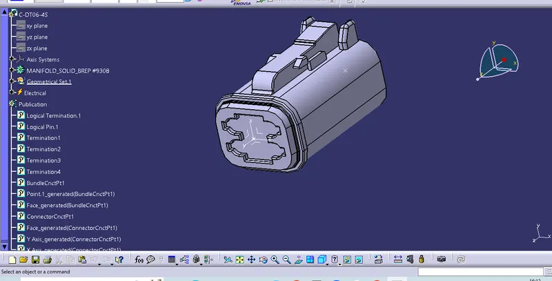
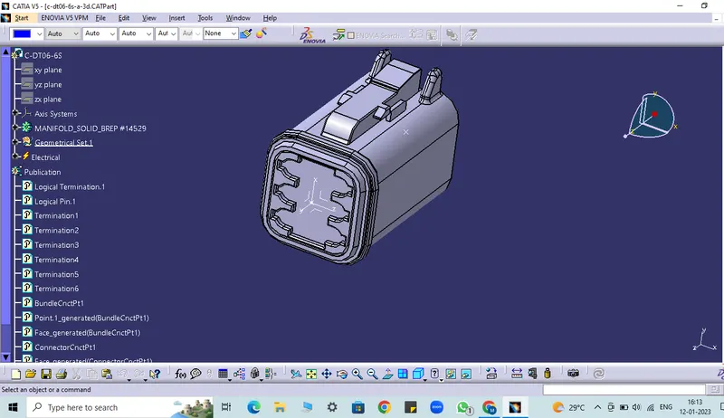
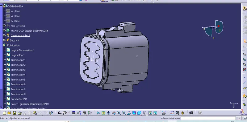
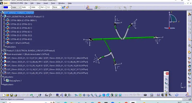
2)A new product file is created and named as'Assembly wiring harness context and two product files are created under it - 'Assembly Geometrical Bundle' and 'Electrical bundle circuit' in the Electrical harness Assembly workbench. All the four defined connectors are inserted into the 'Assembly Geometrical Bundle'. then using the command Geometrical bundle in the Electrical Harness Assembly, they are converted to electrical.
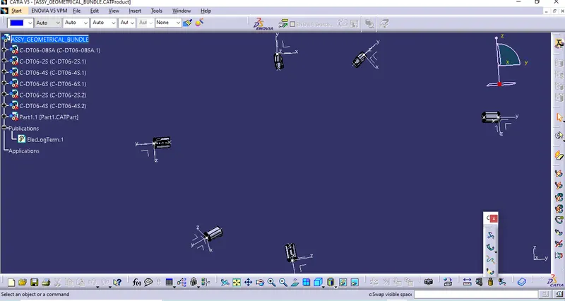
3) Multi-branchable document command is selcted and bundle segments are created. Branch points are selected according to the lengths mentioned in the harness diagram as shown in fig 1. Bundle diameter is assumed to be 15mm and 10mm for diferent branches. Bend ratio is selected as 1.5 and a certain amount of slack is given(3%-5%).
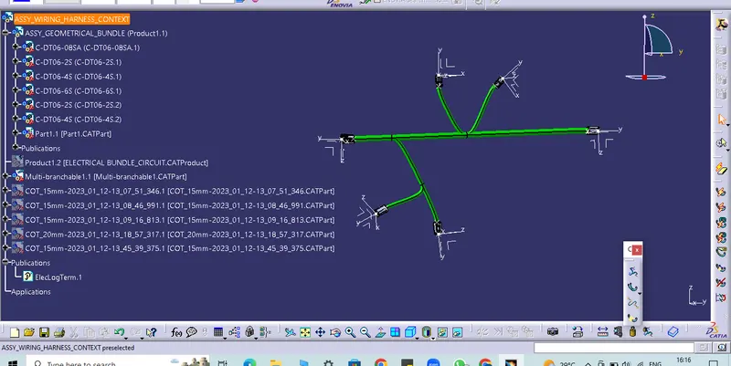
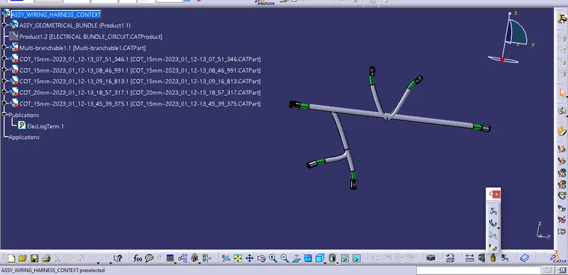
4) Protective coverings are added on all branches connected to DT06-2S & DT06-4S connectors, using the protective covering command. COT of 20mm were selected from the catalogue. End extremity is kept at 30mm away from the bundle entry point.