Wiring harness design in CATIA V5 - 3D modeling Week 4 Challenge
AIM -
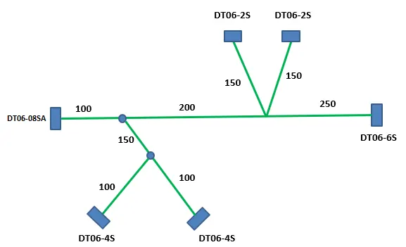
Route the following harness layout in Electrical workbench. Make assumption for harness bundle diameters. Use Following connectors as shown in layout diagram.
Add protective covering on all branches connected to DT06-2S & DT06-4S connectors. Keep end extremity at 30mm (from connectors end)
Download connector 3D data from www.te.com
- DT06-4S
- DT06-6S
- DT06-2S
- DT06-08SA
METHODOLOGY -
1.Preparation of Harness Assembly -
- Create a master product file.
- Insert all the required Surrounding Part data into the Master Product file.
- Save the master product file in a desired location.
2.Creating the Wire harness Geometrical Bundle -
- Select the "Geometrical Bundle" command and then click on Product Icon in Model tree to convert it into an Electrical Assembly.(Ref Image below)

3.Inserting Harness Components into Geometrical Bundle -
- Before Inserting the components, ensure that all the required components have been electrically defined.
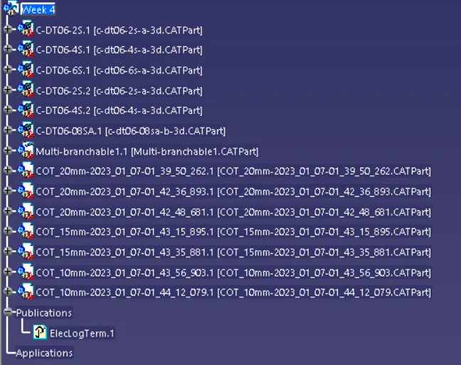
- Once the required components were defined electically, then insert them using Catalog Browser command or using existing component command(ref below image)
4.Positioning the Inserted Components -
- Before start routing, ensure all the components in it's desired location according to surrounding data.
-
If not then place and position the components by using any of the following commands like Manipulation, Translation or Rotation,Snap,Smart Move,Compass.(ref below image).For positioning we can use surrounding data but at last it should not present in routing.

5.Connect and Disconnect Electrical Devices -
- If there are any assembly that need to be assembled before routing like Connector with Mounting Clip or Connector with backshell. Then Assemble them using "Connect Electrical" Devices

6.Defining the Wiring Harness Routing -
Creating Wire Harness with Single Branch -
- Switch to Electrical harness Assembly Workbench.
- Select Multibranchable Document Icon.
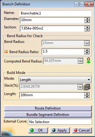
- In the Branch Definition Box(Ref Below Image) ,describe all the required paramters like Diameter,Bend Radius(>1.4),Build mode(slack,Length,Bend,Straight Bend).
- Click Route Definition and select the two components that you need to route.
- Click OK
Creating Wire Harness with Multible Branches:
- Switch to Electrical harness Assembly Workbench.
- Select Multibranchable Document Icon.
- In the Branch Definition Box ,describe all the required paramters like Diameter,Bend Radius(>1.4),Build mode(slack,Length,Bend,Straight Bend).
- Click Route Definition and select the two components that you need to route.
- Click OK.
- Once the Multibranchable is created, Click Add branch point command and define the point on the main branch where the Harness Branch needs to be created.
- Repeat the steps from "3 to 5."
- Add protective covering on the required branches by using Protective Covering Command and mention the start and end extremity points.
CONCLUSION -
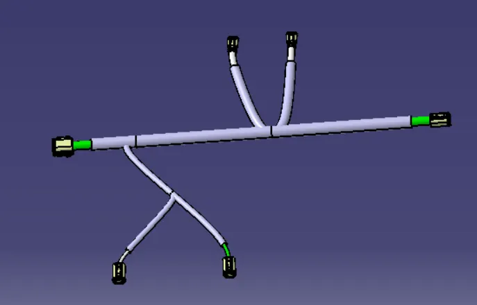
Thus, the Wiring Harness Layout has been designed with the given inputs and the protective coverings also added on the required branches(ref below image)