Wiring harness design in CATIA V5 - 3D modeling Week 4 Challenge
WIRING HARNESS DESIGN IN CATIA V5 - 3D MODELING
Aim: To route the given harness layout in Electrical workbench and add protective covering on all branches connected to DT06-2S & DT06-4S connectors.
1. DT06-08SA Connector
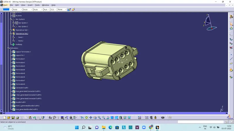
The above figure shows a DT06-08SA Connector, in which the bundle connection point and axis have been defined. Then it is defined as a connector in electrical part design workbench.
2. DT06-6S Connector
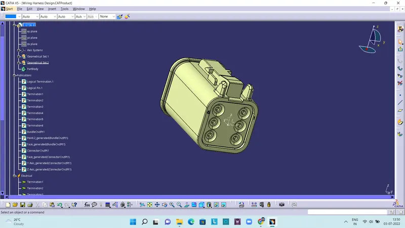
The above figure shows a DT06-6S Connector, in which the bundle connection point and axis have been defined. Then it is defined as a connector in electrical part design workbench.
3. DT06-2S Connector
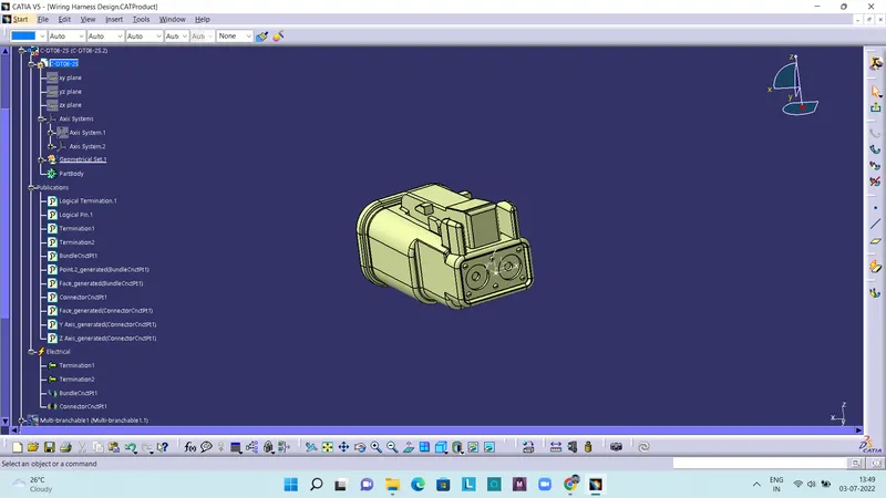
The above figure shows a DT06-2S Connector, in which the bundle connection point and axis have been defined. Then it is defined as a connector in electrical part design workbench.
4. DT06-4S Connector
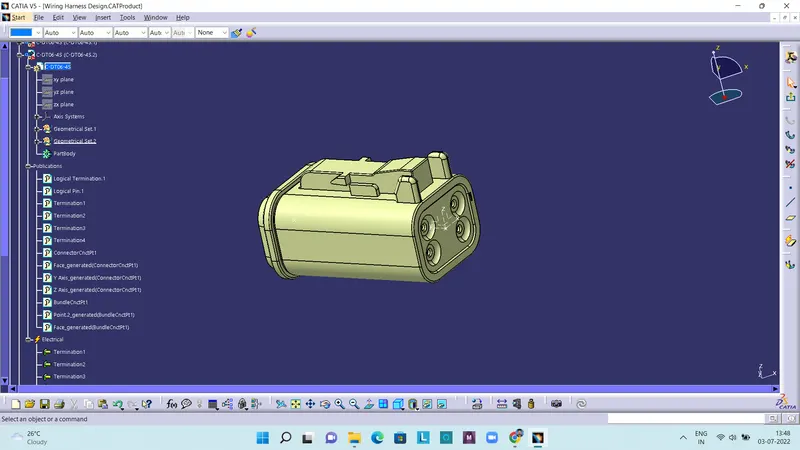
The above figure shows a DT06-4S Connector, in which the bundle connection point and axis have been defined. Then it is defined as a connector in electrical part design workbench. After defining these connectors, they are then stored in a catalogue to use there after.
Electrical Harness Assembly Workbench
Multi-Branchable Document
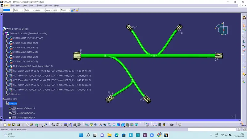
The above figure shows multi branchable connection, the stored connectors from catalogue are first positioned at the given locations and then, the multi branchable document is opened and branch is defined. Here main branch has a diameter of 15mm and sub branches have 10mm diameter.
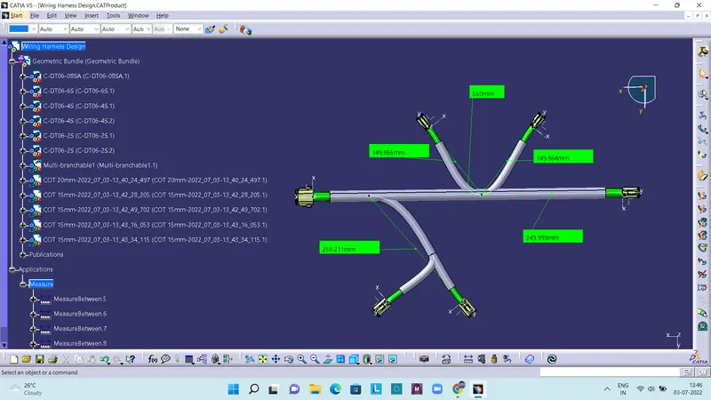
After that the branches are given protective coverings with 20mm and 15mm diameter corrugated tubes.