Wiring harness design in CATIA V5 - 3D modeling Week 4 Challenge
DESIGN OF WIRING HARNESS ROUTING IN CATIA V5
INTRODUCTION
The wiring harness routing consists of an assembly of the geometrical bundle and electrical bundle. For the mechanical wiring harness, assembly of the geometrical bundle is the main component.
For assembly of the geometrical bundle, the connectors, clips, grommets must be electrically defined before entering into the WIRING HARNESS ASSEMBLY.
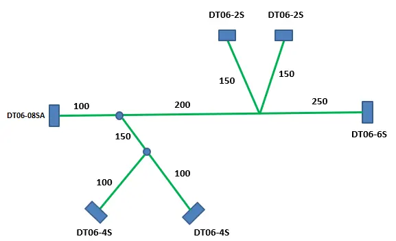
In the present project, the wiring harness for the following mentioned figure
ASSIGN ELECTRICAL PROPERTIES TO CONNECTORS
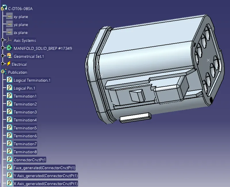
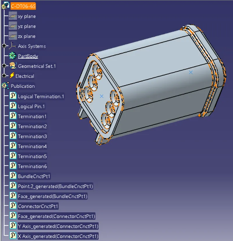
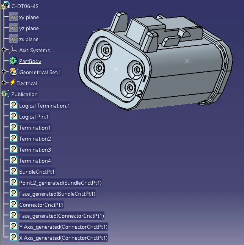
The required connectors are downloaded from te.com. The electrical properties are given to all the connectors using electrical part design.
1) Go to electrical part design.
2) Define the connectors by using the CONNECTORS command.
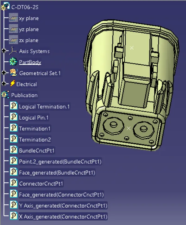
3) Define the CONNECTORS CONNECTION POINT and BUNDLE CONNECTORS POINT to the CONNECTORS.
CREATING WIRING HARNESS
1) Create the assembly of geometrical bundle products in CATIA V5.
2) Open all the required connectors into the geometrical bundle assembly product. Note that all the connectors must be electrically defined.
3) As mentioned in the figure, the connectors are placed al the required positions using the SNAP, SMART MOVE, COORDINATE SYSTEM, and MANIPULATION COMMANDS.
4) Now enter into the WIRING HARNESS ASSEMBLY workbench.
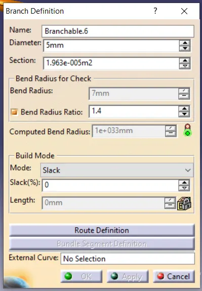
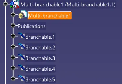
5) Click on MULTI-BRANCHABLE DOCUMENT, give the branch diameter and the bend ratio. Open the route definition and connect the bundle connection points.
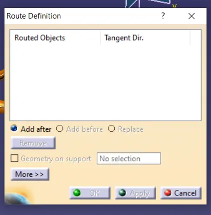
6) To give the routing from main branch use ADD BRANCH POINT at the required location and give the sub-branches.
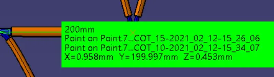
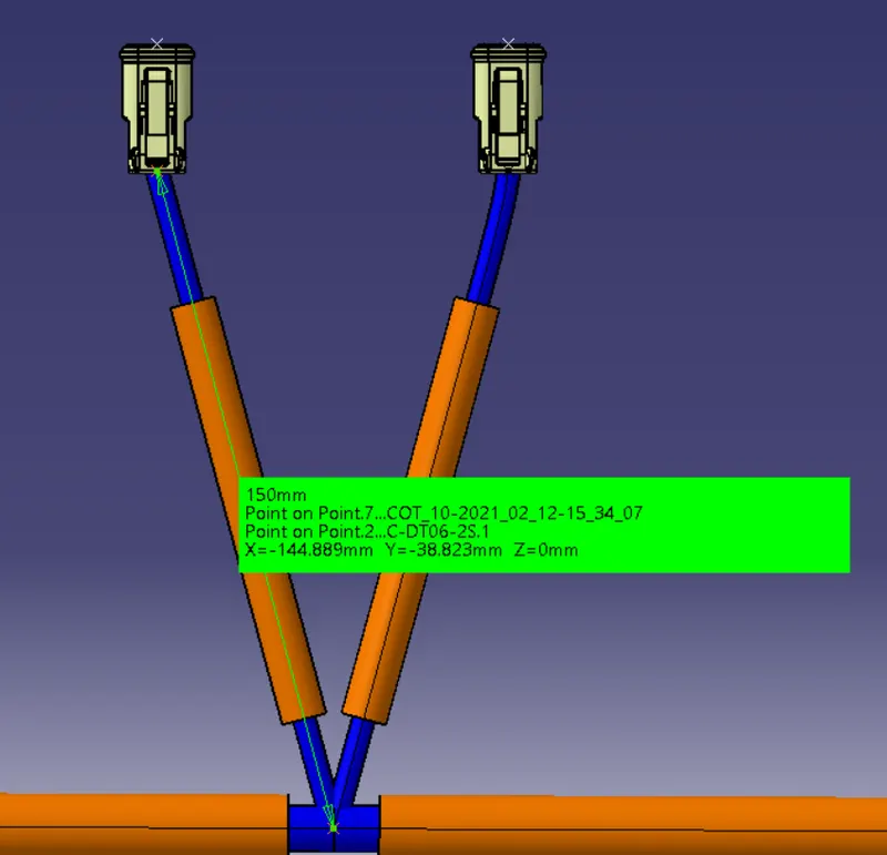
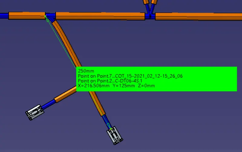
7) Now, add the corrugated tubes which are created and saved in COT_TUBES catalogue.
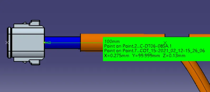
8) Cover all the branches with corrugated tubes. Give the extremity point from 30 mm.
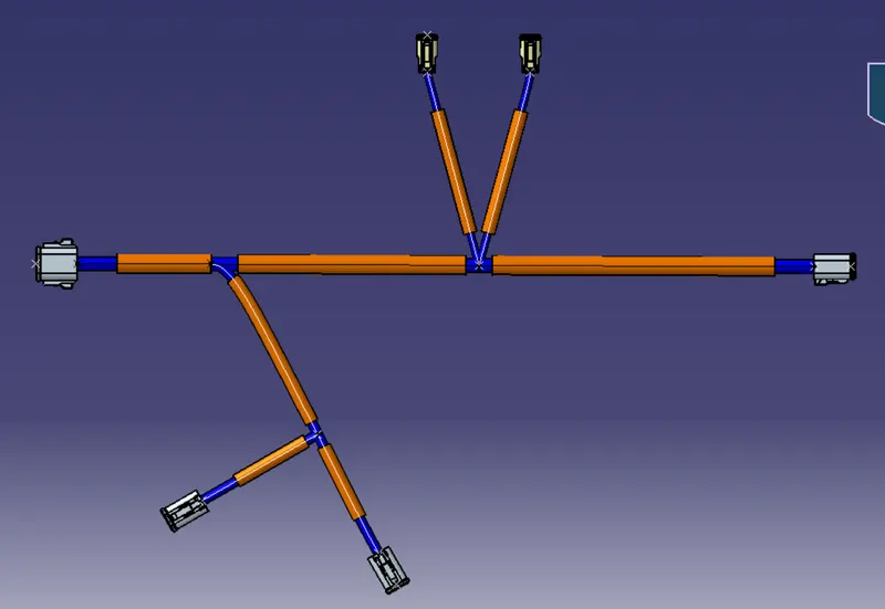
CONCLUSION
The required wiring harness routing has been developed in the CATIA V5.