Project 1
MOLD DESIGN FOR TABLE FAN BASE
1 OBJECTIVE
The objective of the present project is to create a mold for a table fan base using SOLIDWORKS.
2. PROCEDURE
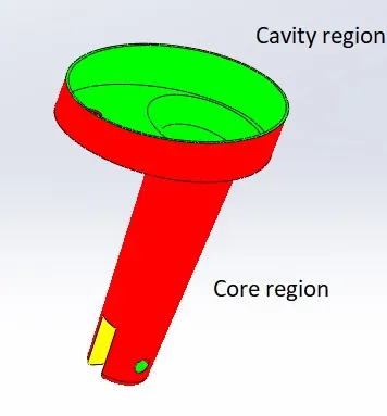
STEP 1: Detecting the direction of cavity and core regions. As a long projection is towards the upper side of the table fan base, this projection is placed inside the core region, and the inner is kept in the cavity region. So, upon removing the core form the cavity region, the part comes down with the core block, and the part removal is easy.
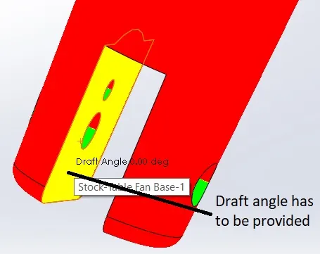
STEP 2: As the part material is ABS, which has 0.6% shrinkage, so a scale of 1.006 is given using the SCALE tool in the mold tools menu.
STEP 3: Using the PARTING LINE tool, a parting line is created. But still, holes are present in the model.
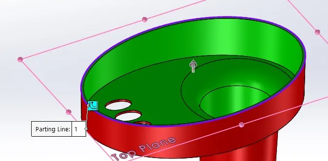
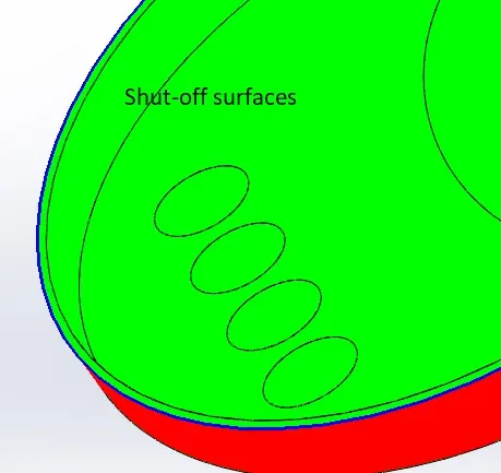
STEP 4: Using SHUT-OFF SURFACES, the holes present in the model are closed near the cavity and core regions meet. Now the parting line is complete.
STEP 5: Using the PARTING SURFACE tool parting surface is created near the parting line.
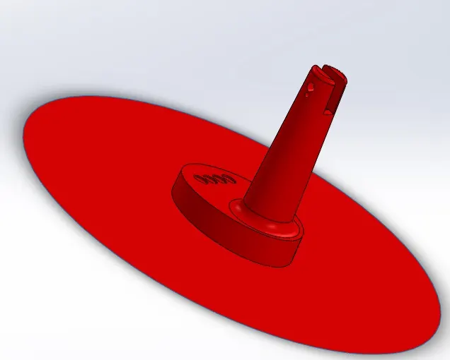
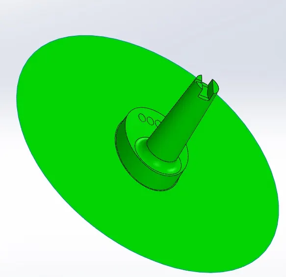
STEP 6: As mold, blocks are designed by different persons in the industry. So the mold blocks are designed in the assembly part. The part is taken into the assembly part, and two new part files are created for cavity and core regions and saved in the same location of the assembly file.
STEP 7: Using the core part file, create the core mold block using the EXTRUDE tool and cut the region with the CUT WITH SURFACE tool. To import the parting surface, the OFFSET SURFACE tool is used. Same as the cavity mold block is also created.
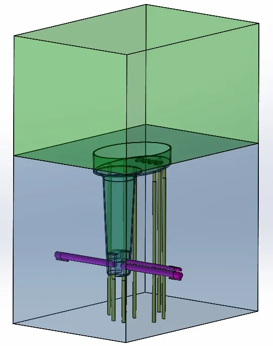
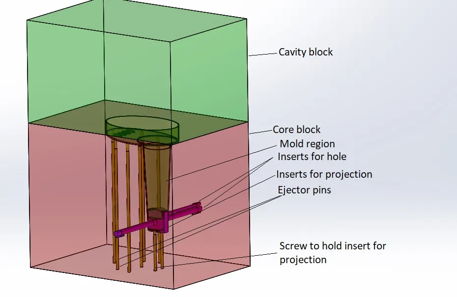
STEP 8: As the projection is in the core block, the ejector pins are created in the core block using the CORE tool. The standard ejector pin of 6 mm is used with a relief of 6.95 mm.
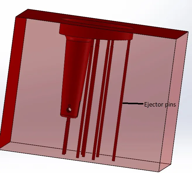
STEP 9: As holes are present in part, it is difficult to fabricate the mold, so circular inserts are used in the mold region for the part to form holes in it. CORE tool is used to create the inserts.
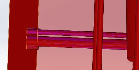
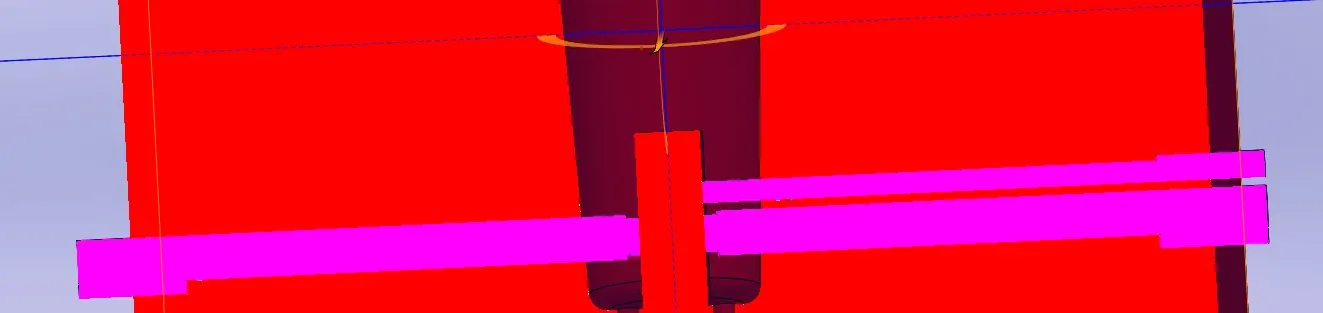
STEP 10: As there is a projection in the core block, it is challenging to fabricate, so an insert is created in the middle of the block, and the region for the projection is created. CORE tool is used.
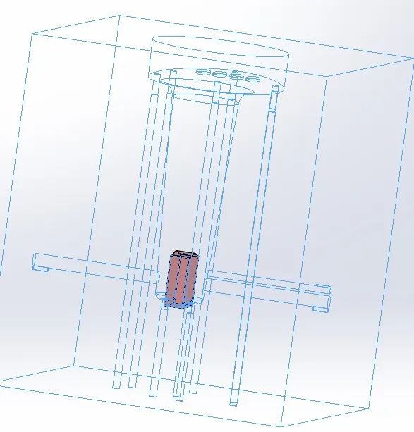
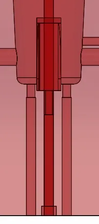
STEP 11: All the parts are separately saved in the assembly file.
3. CONCLUSION
The mold block for the table fan base is created in SOLIDWORKS with ejector pins and inserts.