Wiring harness design in CATIA V5 - 3D modeling Week 2 Challlenge

Automotive Wiring Harness using CATIA V5
REPORT
Assignment-11
By Ravi Ahuja
Objective: To define Connectors and clips as Electrical Connector using Electrical Part design Workbench
Methodology:
- First of all I downloaded the file from the te.com in igs format and then I opened in catia V5 and saved as .CATPart file.
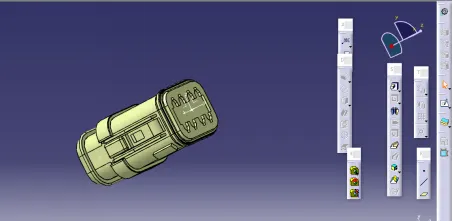
Fig. File saved as CATPart
- I started with adding points on the bundle connection point and Connector connection point in part design
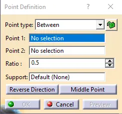
Fig. Point definition
- I selected corresponding reference points to get a point at the center of the entry of the bundle and connector connection region.
- Then I created different axis system at the point of bundle connection to define the Bundle entry point and initial point.
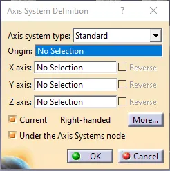
Fig. Axis system definition
- After creating axis systems I switched to the electrical part design.
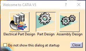
Fig. Switching to electrical part design
- I selected the define connector option in the toolbar. Selected the part body and dialog box appeared like this.
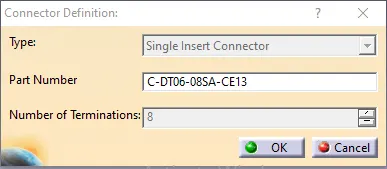
Fig. Defining connector
- Then I mentioned the number of terminations and type of connector as Single insert type connector.
- Then I selected the define bundle connection point feature fro the toolbar. Then selected the part body and dialog box appeared.
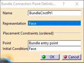
Fig. Defining bundle entry point
- After that I selected the face as representation and the point we created as point for constraints and then face as initial condition.
- Then I selected the define connector connection point feature in toolbar to define the connector connection point.
- Then I selected the part body and dialog box appeared.
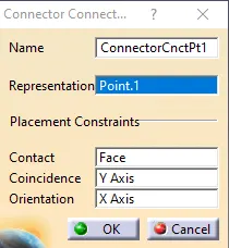
Fig. defining connector connection point
- Then I selected the point as the representation, face as contact, Coincidence as Y axis and Orientation as X axis from the newly created axis system.
- Now the component is defined as a connector with bundle entry point and connector connection point and orientation.
- After this process the feature tree is like this showing every feature and published details.
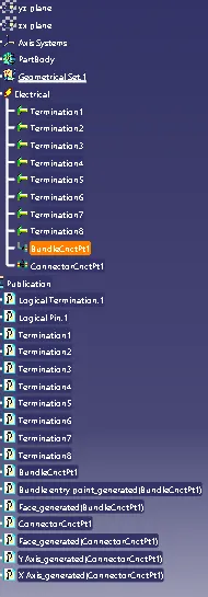
Fig. Feature tree
- All the components follow the same step and we define each component as shown above.