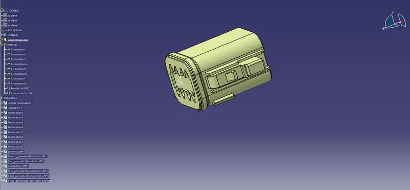
Wiring harness design in CATIA V5 - 3D modeling Week 2 Challlenge
To define Deutsch DT06 – 08SA as a electrical connector and properties.
-Import the part to the mechanical part design.
-Define the center point of both the end for a reference. point can be applied in the connector end by clicking on the point icon on the references element toolbar.
-On the dialog box select the point type as between and for point 1 and point 2 click on the diagonal points and click on mid point.And click on ok. Point is created.
-In the similar way we are creating point in the bundle end.
- Now we are creating axis in the connector side. By clicking on axis system in the tools toolbar.
-Set the axis system type as standard .For orgin click on the pont we have created in the middle of the face.for the orientation of the x and y axis rotate the x axis by 90 deg and y axis to 180 deg by right clicking mouse on the axis tab and click the rotation.
-Now change to eletrical part design window by click on electrical part design in workbench toolbar.
-Define the element as a connector by clicking the define connector in the electrical device definition toolbar.
-Dialog box will appear as we click on the cad model.In the connector definition box select single insert connector as the type.
-Enter the part number in the part number field.Enter the number of termination as 8.
-To define the Bundle connection point.Click on the bundle connection point icon from the electrical device definition toolbar.
Select the connector.A dialog box with appear. Click on representation tab and click on the face of the bundle.
-In the placement constraints select the point as the point on the middle of the bundle face as the initial condition as the face.
-To define the connector connection point.Click on the connector connection point icon from the electrical device definition toolbar.select the connector.A dialog box with appear.
-Click on representation tab and click on the face of the connector.for the placement constraints select the face as contact,coincidence as y axis and for orientation as x axis.
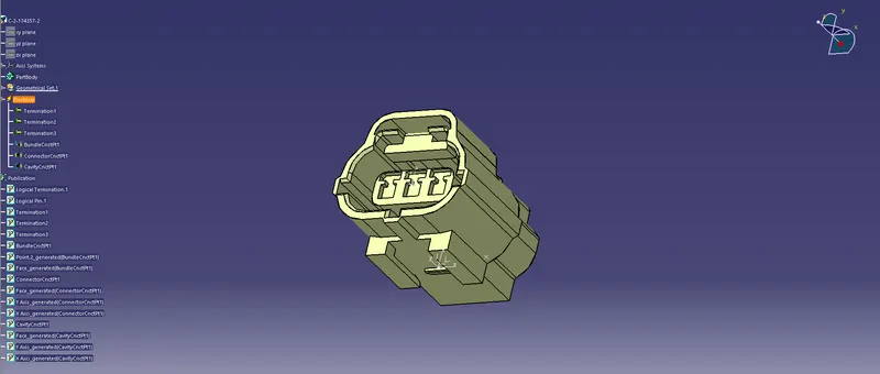
To define Tyco 174357-2 – 08SA as a electrical connector and properties.
-Import the part to the mechanical part design.Here we define the center point of both the end for a reference.
-Point can be applied in the connector end by clicking on the point icon on the references element toolbar.On the dialog box select the point type as between and for point 1 and point 2 click on the diagonal points and click on mid point.And click on ok. Point is created.
-In the bundle end select the point type as circle/sphere/ellipse center and click on the circumference the bundle to create a point.Also we need to create a point in the mating side by selecting between as point type and selectiing the mating edge and select mid point.
- now we are creating axis in the connector side. By clicking on axis system in the tools toolbar.set the axis system type as standard .For orgin click on the pont we have created in the middle of the face
-For the orientation of the x and y axis rotate the x axis by 90 deg and y axis to 90 deg by right clicking mouse on the axis tab and click the rotation.Also we need to create a axis in the mating side. select the point as orgin and click on ok.
-Now change to eletrical part design window by click on electrical part design in workbench toolbar.
-Define the element as a connector by clicking the define connector in the electrical device definition toolbar.A dialog box will appear as we click on the cad model.
-In the connector definition box select single insert connector as the type.Enter the part number in the part number field.Enter the number of termination as 3.
-To define the Bundle connection point.Click on the bundle connection point icon from the electrical device definition toolbar.select the connector.A dialog box with appear. Click on representation tab and click on the face of the bundle.
For the placement constraints select the point as the point on the middle of the bundle face as the initial condition as the face.
-To define the connector connection point.Click on the connector connection point icon from the electrical device definition toolbar.select the connector.A dialog box with appear. Click on representation tab and click on the point in the face of connector.
For the placement constraints select the face as contact,coincidence as y axis and for orientation as x axis.
-To define the cavity connection point.Click on the cavity connection point icon from the electrical device definition toolbar.select the model.A dialog box with appear.
-Click on representation tab and click on the point in the face of mating face.for the placement constraints select the face as contact,coincidence as y axis and for orientation as x axis.
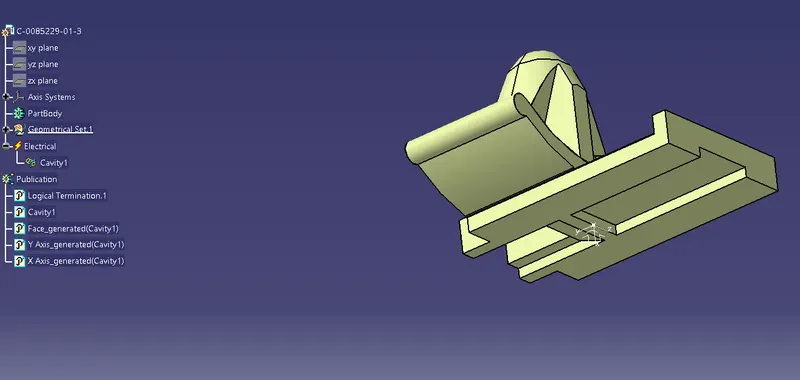
To define Tyco Tyco 85229-1 – 08SA as a electrical connector and properties.
-Import the part to the mechanical part design.Here we define the point for a reference.Selecting the point in the reference element toolbar.Selecting point type as between.
-Selecting the edge of mating face and selecting mid point.Point is created.
- Creating by clicking on axis system in the tools toolbar.set the axis system type as standard .For orgin click on the pont we have created in the middle of the face.
-For the orientation of the x and y axis rotate the x axis by 180 deg and y axis to 270 deg by right clicking mouse on the axis tab and click the rotation.
-Now change to eletrical part design window by click on electrical part design in workbench toolbar.
-To define the cavity connection point.Click on the cavity connection point icon from the electrical device definition toolbar.select the model.A dialog box with appear. Click on representation tab and click on the point in the face of mating face.
-In placement constraints select the face as contact,coincidence as y axis and for orientation as x axis.