Wiring harness design in CATIA V5 - 3D modeling Week 2 Challlenge
WIRING HARNESS WEEK 2 CHALLENGE
Electrical Distribution System, EDS, deals with the physical and logical architecture, schematic development, power distribution, and wiring harness design of an electrical system.
In this challenge, CAD data for connectors and connector clip were downloaded and defined as Electrical Connectors using the Electrical Part design workbench.
STEPS
After the CAD data were downloaded and unzipped, certain tasks including Connector Definition were performed.
GEOMETRICAL PARAMETERS
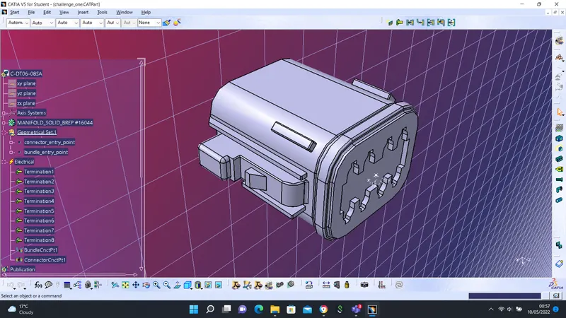
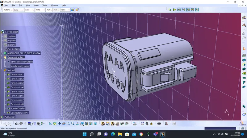
Certain parameters including point and axis definitions were defined both for bundle connector and connection connector.
PART CONNECTOR DEFINITION
After certain geometrical parameters were defined, it was switched to Electrical Part Design Workbench where the part was defined as a Connector.
BUNDLE CONNECTION POINT
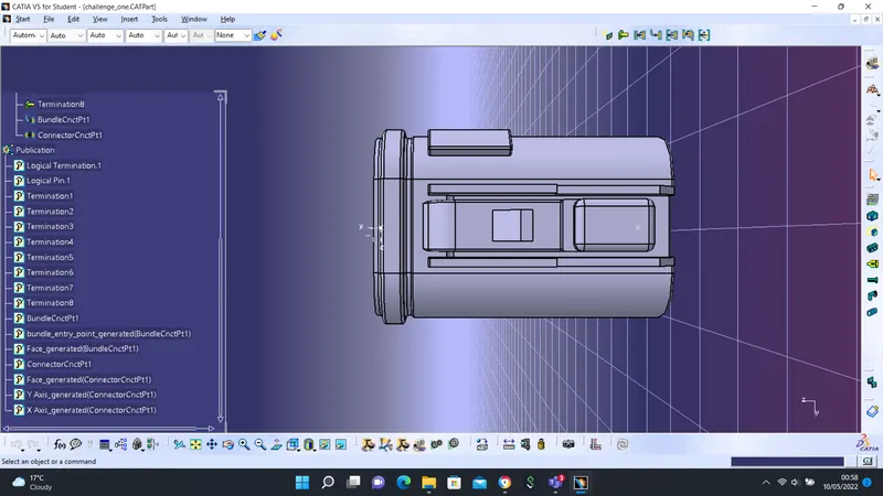
The bundle connection point was defined using the point created. The appropriate face was also selected.
CONNECTOR CONNECTION POINT
Connector Connection Point was created equally with the point reference. In this task, Cavity Connection Point was not created as there is no clip mounting feature on the connector.
TASK 2
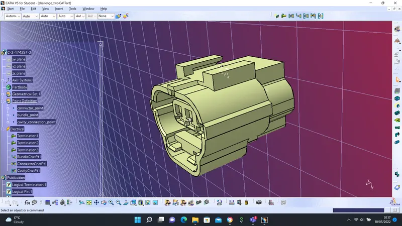
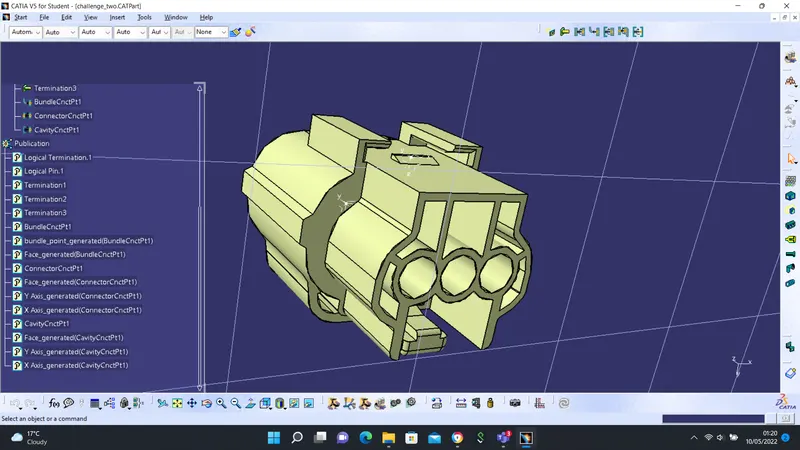
In this part, certain tasks were performed which include:
- creating geometrical parameter
- defining connector
- defining bundle connector point
- the defining connector connection point
- the defining cavity connection point
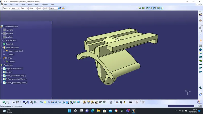
CLIP
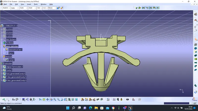
Point and axis geometry was performed on the clip.
- creating geometrical parameter
- defining connector
- defining bundle connector point
- the defining connector connection point
- the defining cavity
ASSEMBLY
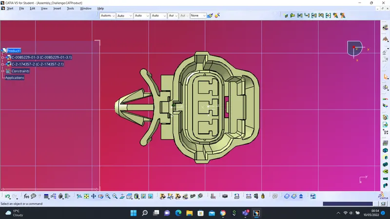
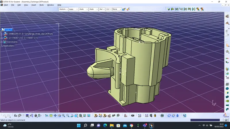
Using the Electrical Assembly Design workbench, both the connector and the clip were assembled. To assemble, the reference point for both were connected using Connect Electrical Device command.