Wiring harness design in CATIA V5 - 3D modeling Week 2 Challenge
AIM:
To download following connectors & Connector clip cad files form the te.com website and then defining the Electrical Connector using Electrical Part design Workbench. and further creating a catalogue for the components.
INTRODUCTION:
WIRING HARNESS:
A wiring harness, also known as a cable harness or wiring loom, is a structured assembly of wires or cables that transmit electrical power and signals within various systems. It consists of multiple cables or wires bound together with cable ties, sleeves, or conduit to organize and protect them from damage due to abrasion, moisture, heat, and other environmental factors. Wiring harnesses are commonly used in automotive, aerospace, industrial machinery, and electronics applications.
CONNECTOR:
Components of an Electrical Circuit are electrically connected if an Electrical Current can run between them through an Electrical Conductor. An electrical connector is an electro mechanical device used to create an electrical connection between parts of an electrical circuit, or between different electrical circuits, thereby joining them into a larger circuit.
CONNECTOR CLIP:
Made from thermoplastic, they help secure the mounting of the connectors under the hood of a vehicle or on the chassis.
SPECIFICATION:
CONNECTOR:
- Deutsch DT06 – 08SA
- Tyco 174357-2
CONNECTOR CLIP:
- Tyco 85229-1
For connector-1
Deutsch DT06 – 08SA
STEP-1
Download the connector cad files form the te.com website. Image mention below.
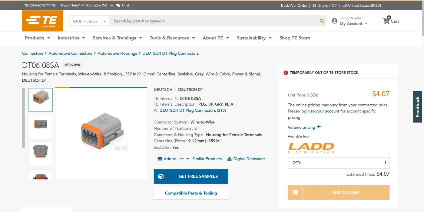
Download the stp or igs file and open into the catia V5.
STEP-2
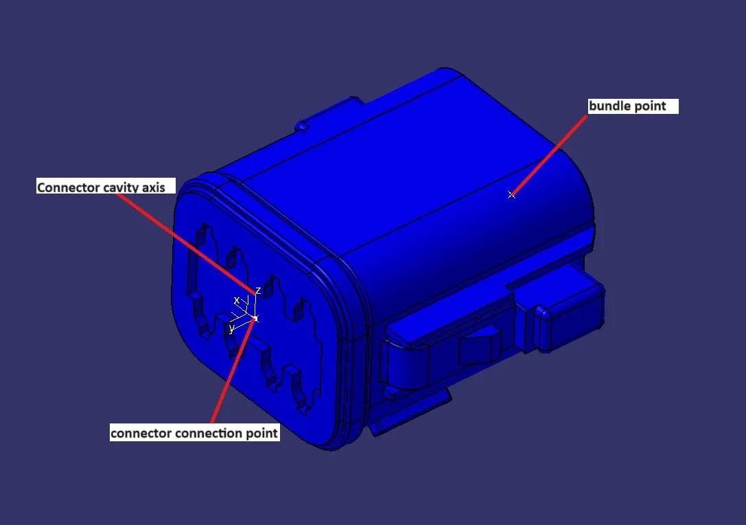
Create the required geometrical parameters for the part like connector connection point and bundle entry points andConnector cavity axis. To do that we have to first assign a mid-point to the bundle connection side face of the connector and then we also have to assign a mid-point to connector connection side of the connector, along with that we also have to assign an axis system on the mid-point of the connector connection side face for creating axis y- axis always in the mating face direction x- axis should be in locking side direction . This will allow us to fully define our connector geometrically.
STEP-3
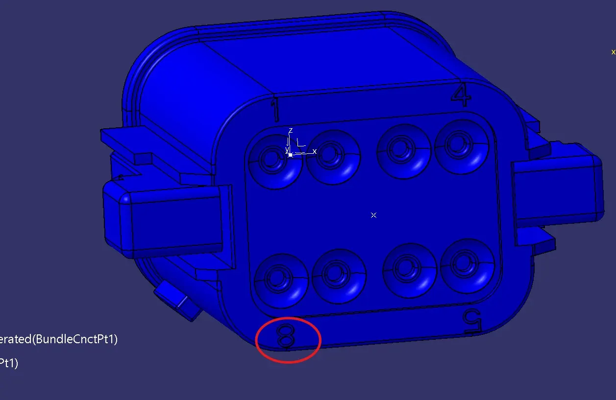
After creating the points we have to start the Electrical Part Design Workbench in Catia to define the connector electrically. for that we select the define connector option from the toolbars and then we select the connector body and also assign the number of terminals to the connector which in this case are 8 terminals. image mention below.
STEP-4
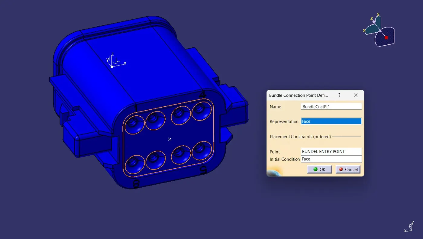
Then we select the define bundle connection point option from the toolbars and then we select the connector body, bundle contact face for representation, mid-point for point, and again bundle contact face for initial condition and then click on ok. image mention below.
STEP-5
And finally we select the define connector connection point option from the toolbars and then we select the connector body, mid-point for representation, contact face for contact, Y-axis for coincidence and X- axis for orientation and then click on ok. image mention below.
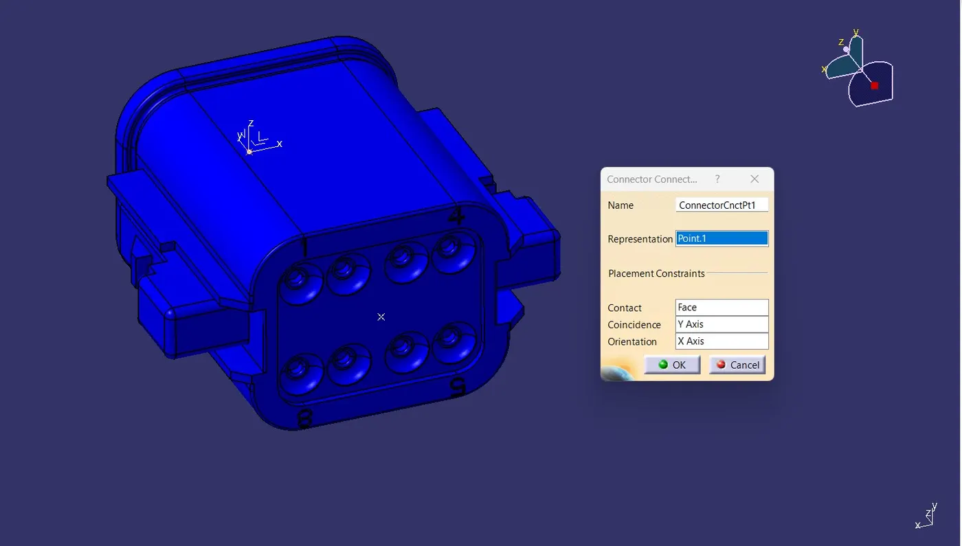
And save the file.
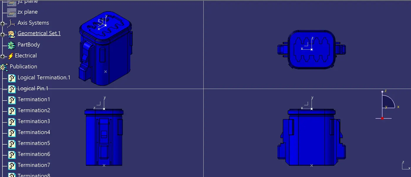
For connector-2
Tyco 174357-2
STEP-1
Download the connector cad files form the te.com website. Image mention below.
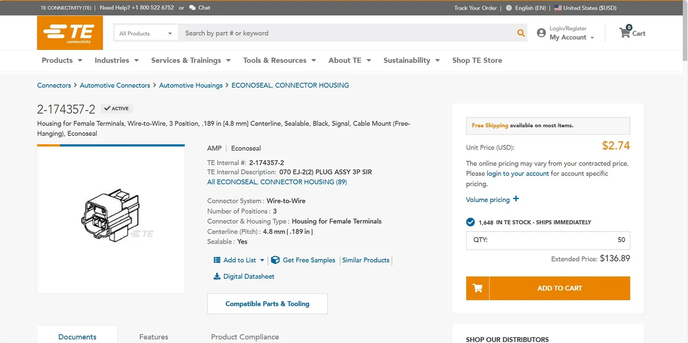
Download the stp or igs file and open into the catia V5.
STEP-2
First open the 3D CAD data in Catia and then convert the file format(ex: .igs,.stp) to .CATPart.
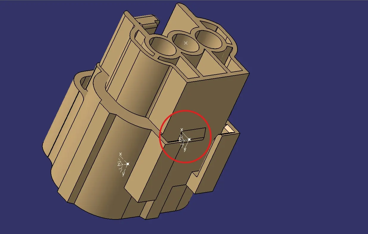
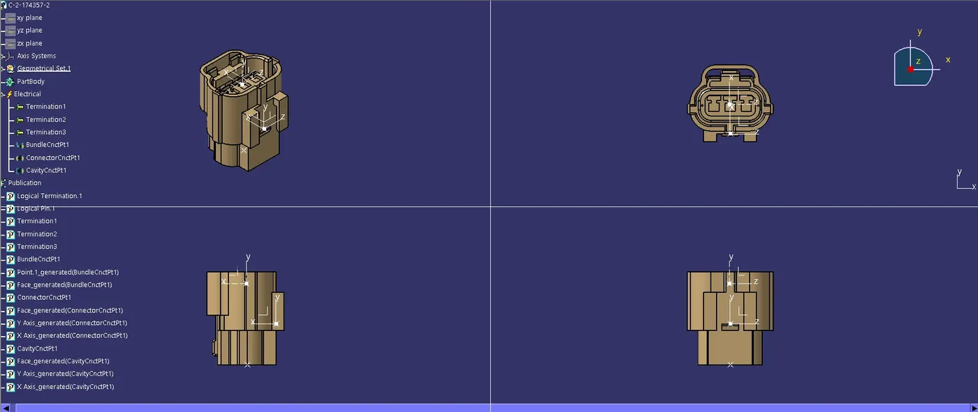
Then define the connector geometrically in the Catia Part Design Workbench. To do that we have to first assign a mid-point to the bundle connection side face of the connector and then we also have to assign a mid-point to connector connection side of the connector, along with that we also have to assign an axis system on the mid-point of the connector connection side face. image mention below.
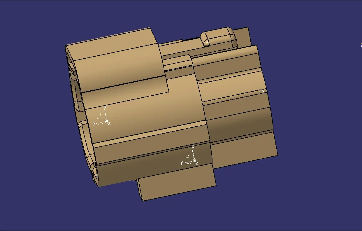
Also we have to create a mating reference at the bottom side of the connector so that we can mount a clip onto the connectors. To do that we can just create a mid-point and an axis system with that mid-point as reference on the face which will have contact with the clip. image mention below.
STEP-3
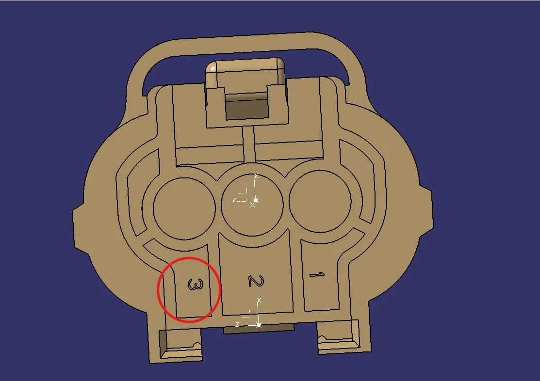
After that start the Electrical Part Design Workbench in Catia to define the connector electrically.
First we select the define connector option from the toolbars and then we select the connector body and also assign the number of terminals to the connector which in this case are 3 terminals. image mention below.
STEP-4
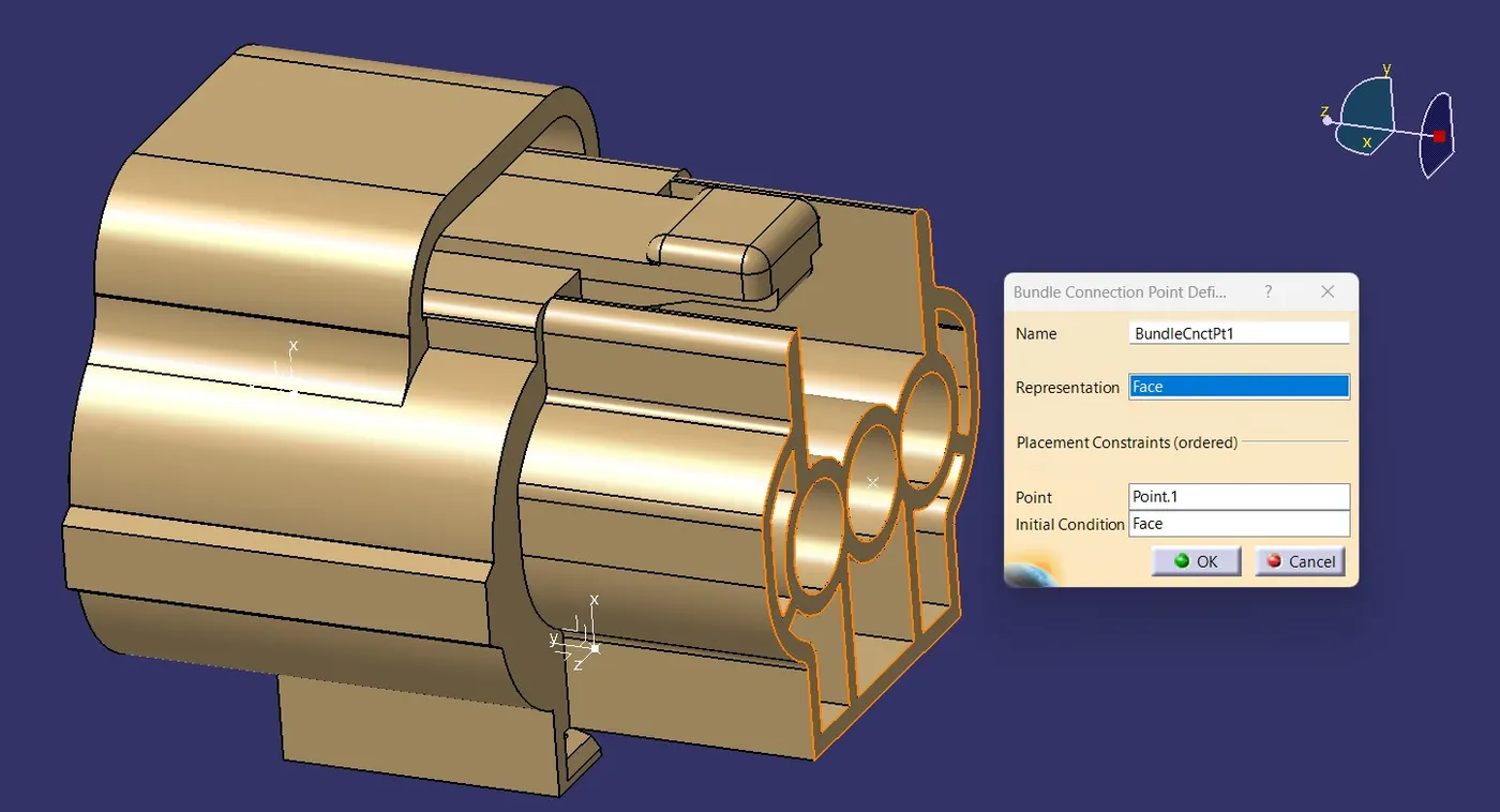
Then we select the define bundle connection point option from the toolbars and then we select the connector body, bundle contact face for representation, mid-point for point, and again bundle contact face for initial condition and then click on ok. image mention below.
STEP-5
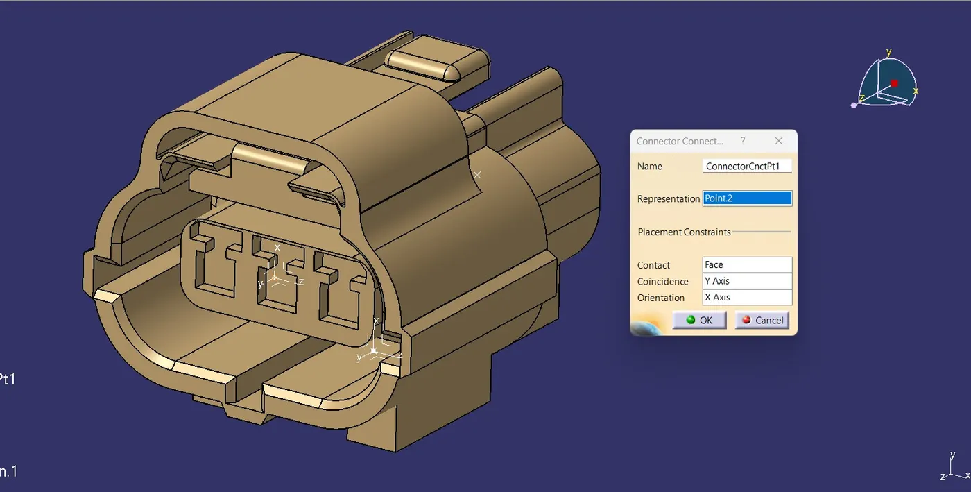
Then we select the define connector connection point option from the toolbars and then we select the connector body, mid-point for representation, contact face for contact, Y-axis for coincidence and X- axis for orientation and then click on ok. image mention below.
STEP-6
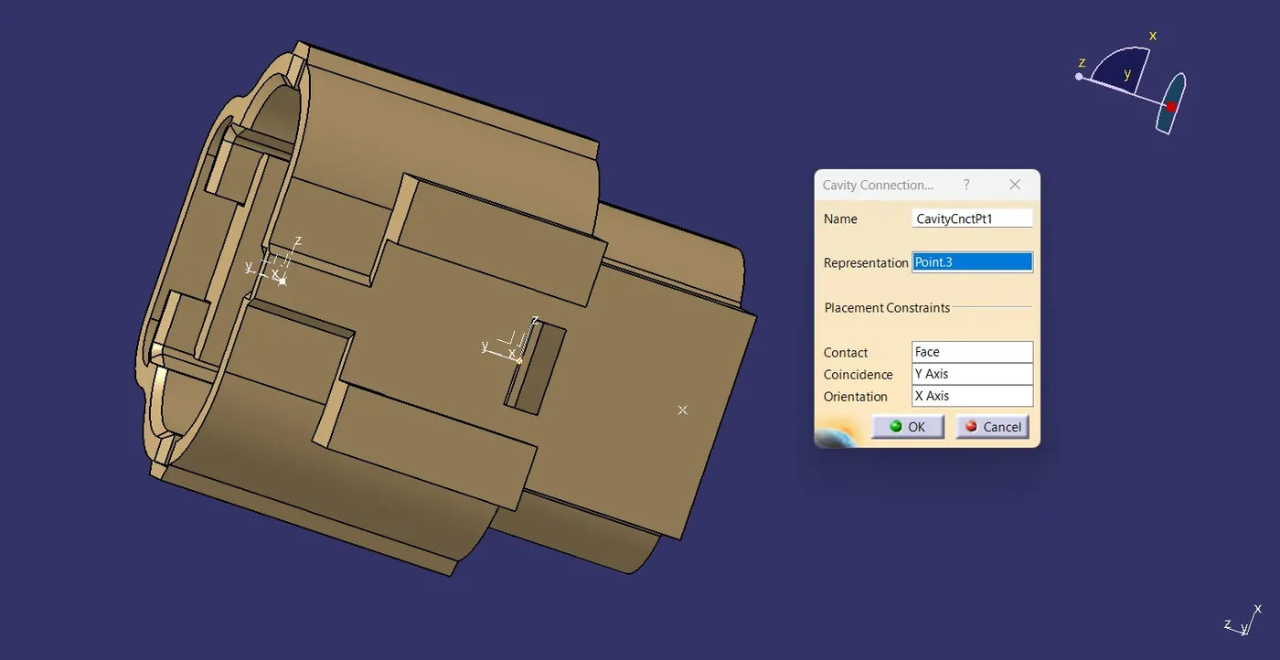
Then we select the define cavity connection point option from the toolbars and then we select the connector body, bottom side mid-point as representation, mating face for contact, Y-axis for coincidence and X- axis for orientation and then click on ok. This will fully define our connector electrically. image mention below.
And save the file.
Tyco 85229-1
STEP-1
Download the connector clip cad files form the te.com website. Image mention below.
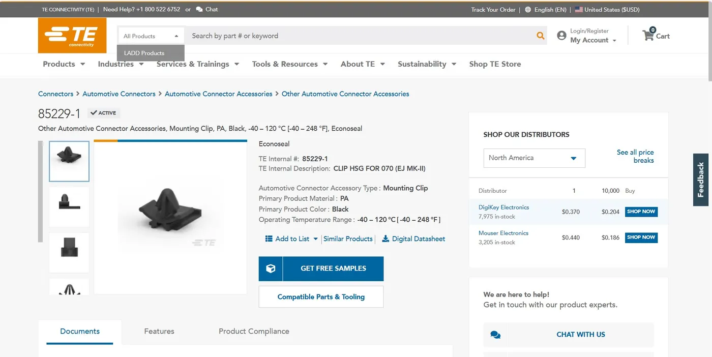
Download the stp or igs file and open into the catia V5.
STEP-2
First open the 3D CAD data in Catia and then convert the file format(ex: .igs,.stp) to .CATPart.
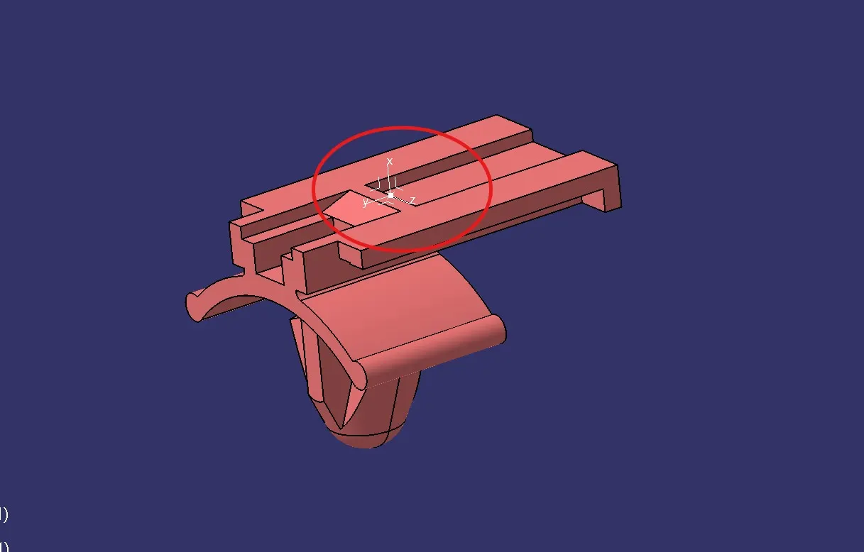
Then define the clip geometrically in the Catia Part Design Workbench. To do that we can just create a mid-point and an axis system with that mid-point as reference on the face which will have contact with the connector. This will allow us to fully define our clip geometrically. image mention below.
STEP-3
After that start the Electrical Part Design Workbench in Catia to define the clip electrically.First we select the define mounting equipment option from the toolbars and then we select the clip.
Then we select the define cavity option from the toolbars and then select the clip body, mid-point for representation, contact face for contact, Y-axis for coincidence and X- axis for orientation and then click on ok. Image mention below.
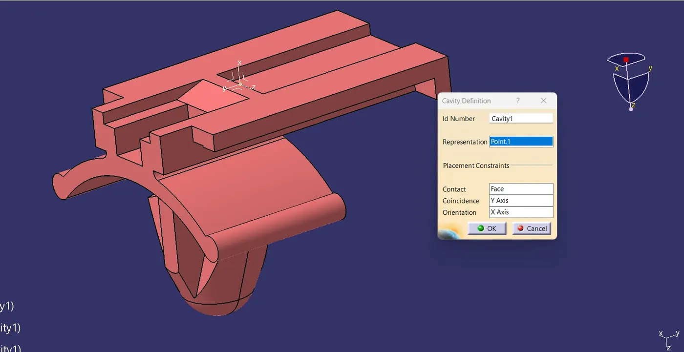
And save the file.
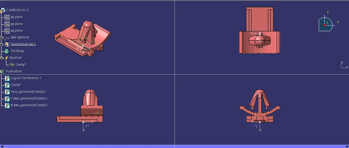
FOR CONNECTOR AND CONNECTOR CLIP ASSEMBLY:
Start the Electrical Assembly Design Workbench in Catia. Copy the connector and connector clip parts and paste in the assembly tree. Rotate both the models in order to give them proper orientation so that they can come in contact properly. Select the connect electrical devices option from the toolbars and then select the connector and clip to mount then together.
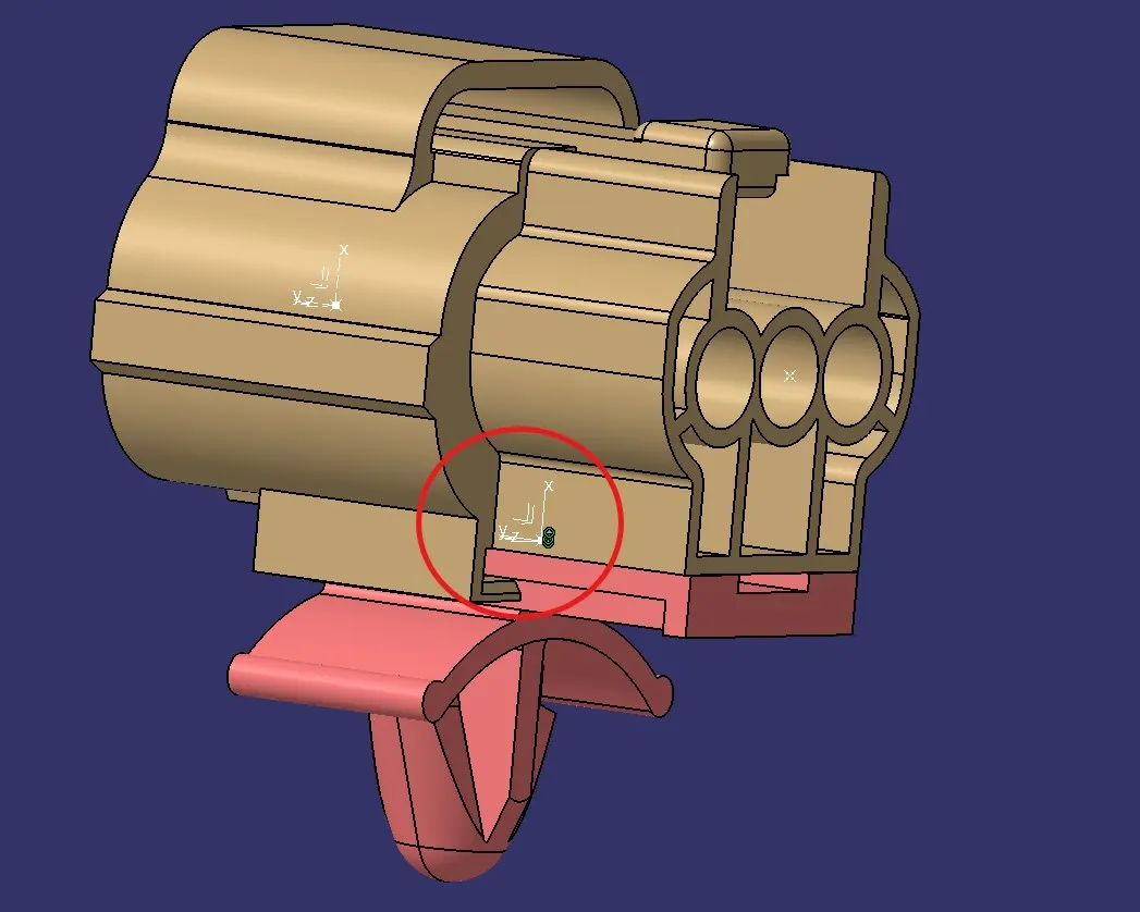
Tyco 174357-2 and Tyco 85229-1 Assembly view image mention below.
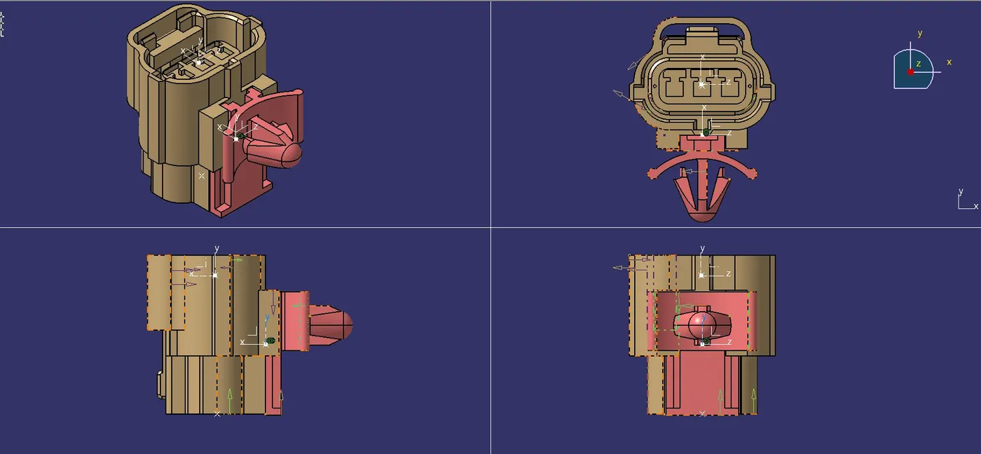
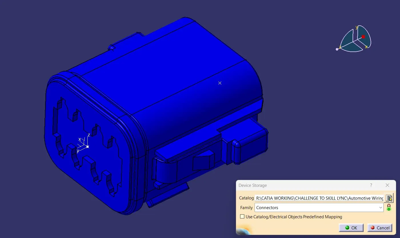
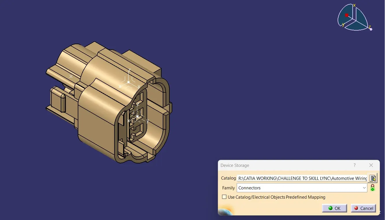
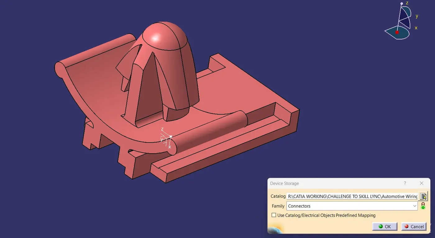
And further creating the catalogue for these components image mention below.
CONCLUSION:
Finally we download following connectors & Connector clip cad files form the te.com website and then define the the Electrical Connector using Electrical Part design Workbench. and further creating a catalogue for the components.