Wiring harness design in CATIA V5 - 3D modeling Week 2 Challenge
Wiring harness:
A wire harness, often referred to as a cable harness or wiring assembly, is a systematic and integrated arrangement of cables within an insulated material. The purpose of the assembly is to transmit signal or electrical power. Cables are bound together with straps, cable ties, cable lacing, sleeves, electrical tape, conduit, or a combination thereof. The wire harness simplifies the connection to larger components by integrating the wiring into a single unit for “drop-in” installation. A wiring harness consists of different sets of connectors like terminals and wires which run through the entire vehicle and transmit information.
A wire harness process is designed based on the geometric and electrical requirements of the equipment it is to be installed in. Once the initial design is established, a schematic is used to create the manufacturing paperwork and the assembly board for the harness. The assembly board, also called a pin board, is a full-size diagram of the harness that shows all of the components and their locations. It also serves as the workbench for the harness.
Connectors:
A connector is a coupling device that joins electrical terminations to create an electrical circuit. Connectors enable contact between wires, cables, printed circuit boards, and electronic components that are engineered to reliably transmit data, power, and signal in the harshest environments. It offers to withstand harsh conditions, retention, EMI shielding and reduces application size and power usage while enabling increased performance.
Defining the connector
We need to define the connector by following the below steps.
- Download the connector data.
- Create required geometrical parameter.
- Define part as electrical connector.
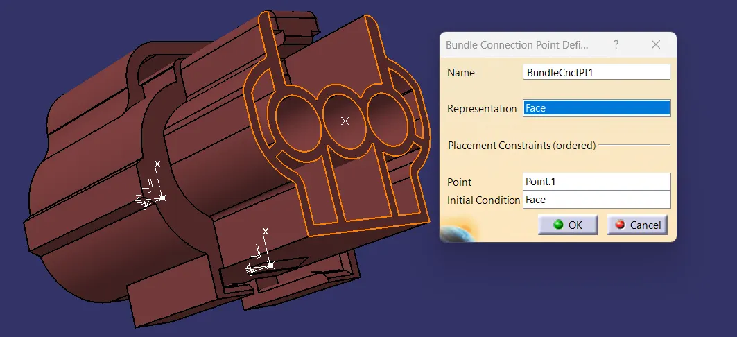
- Define bundle connection point.
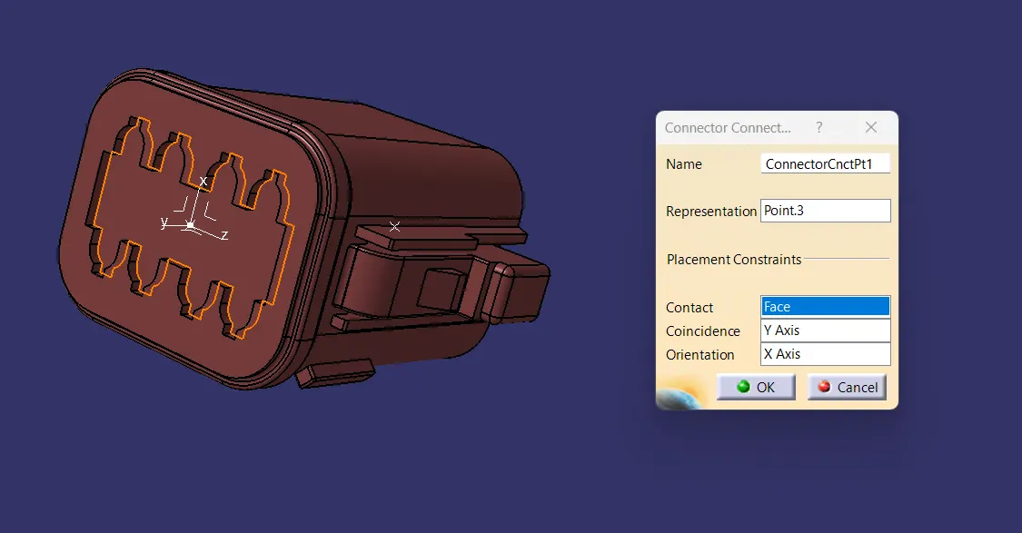
- Define connector connection point.
- Define cavity connection point.
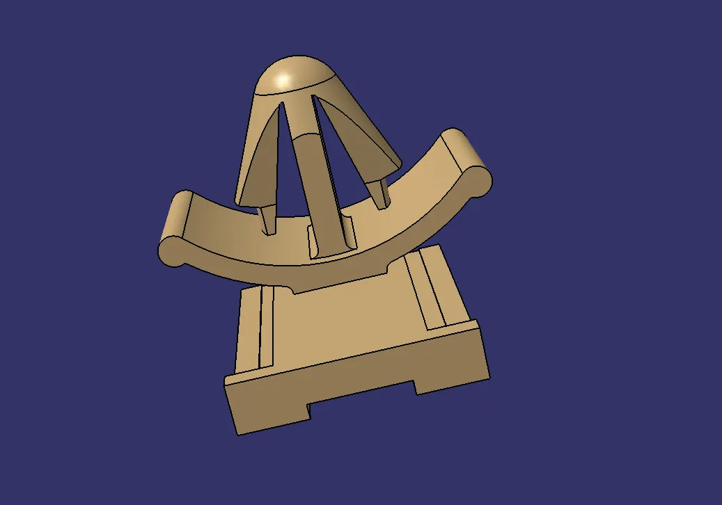
Defining the mounting clip
- Download the clip 3d data.
- Create the geometry parameter.
- Define the part as mounting component.
- Define the part as cavity.
Defining the connector is described below
- Downloaded the cad data from the supplier's website and the images are shown below.
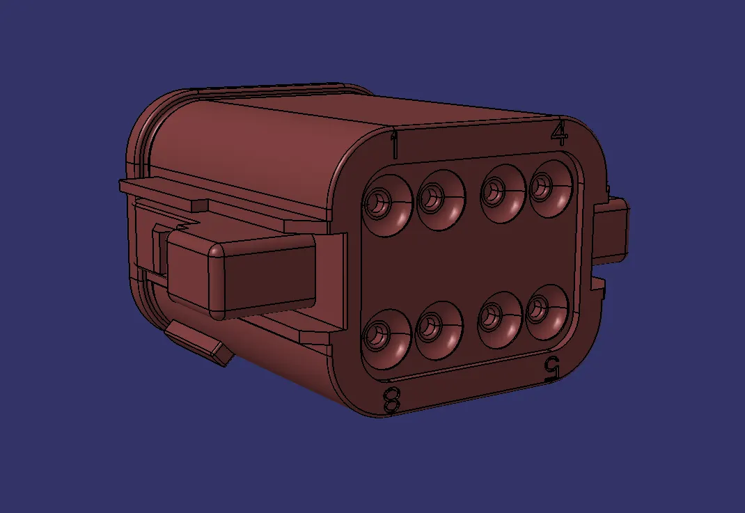
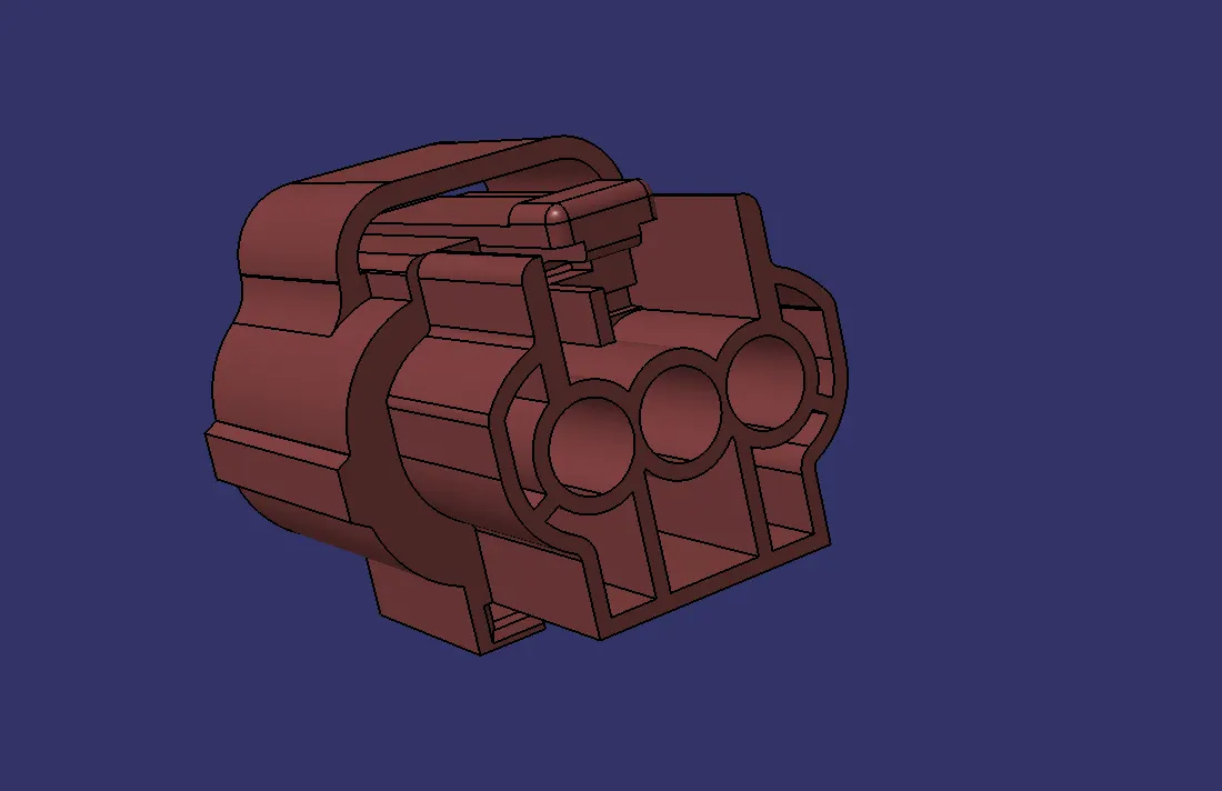
- Creating required geometrical parameters for the connectors
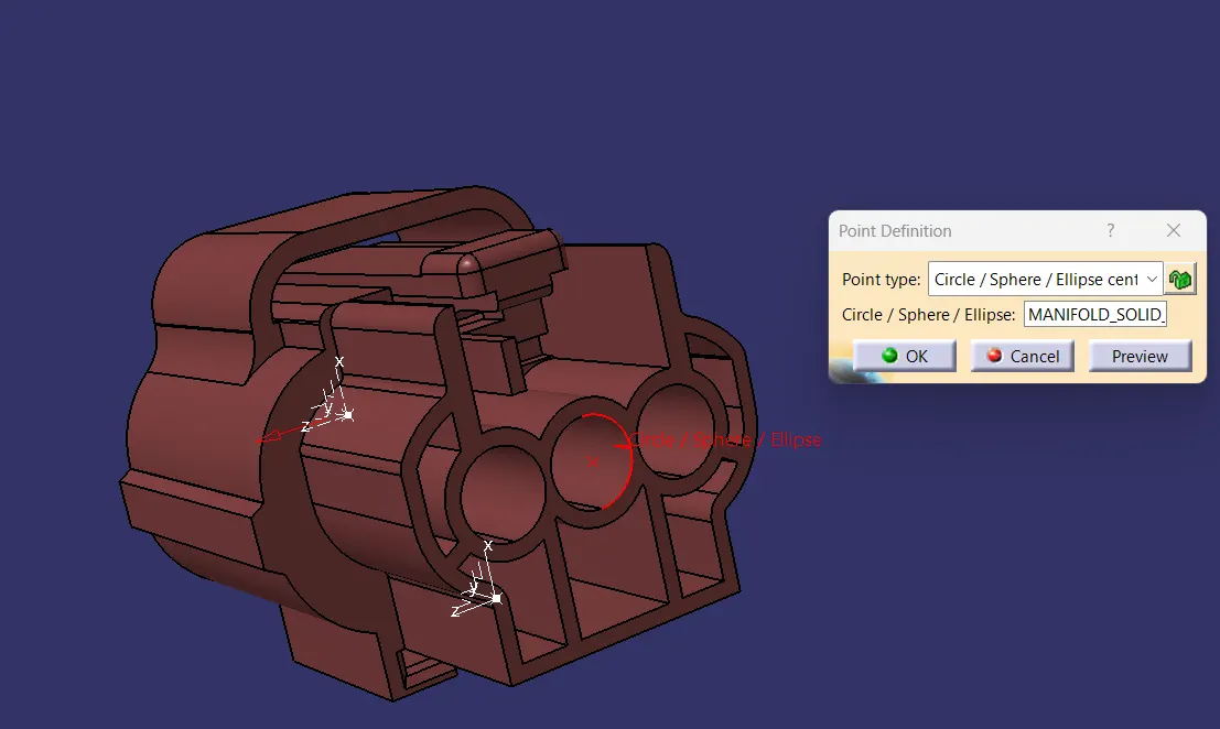
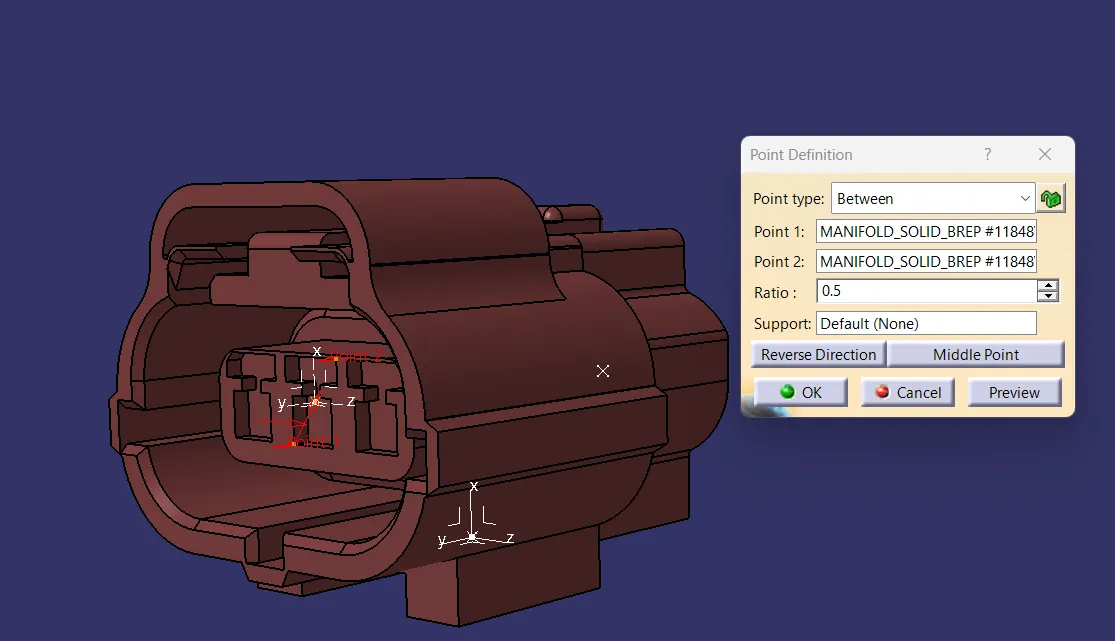
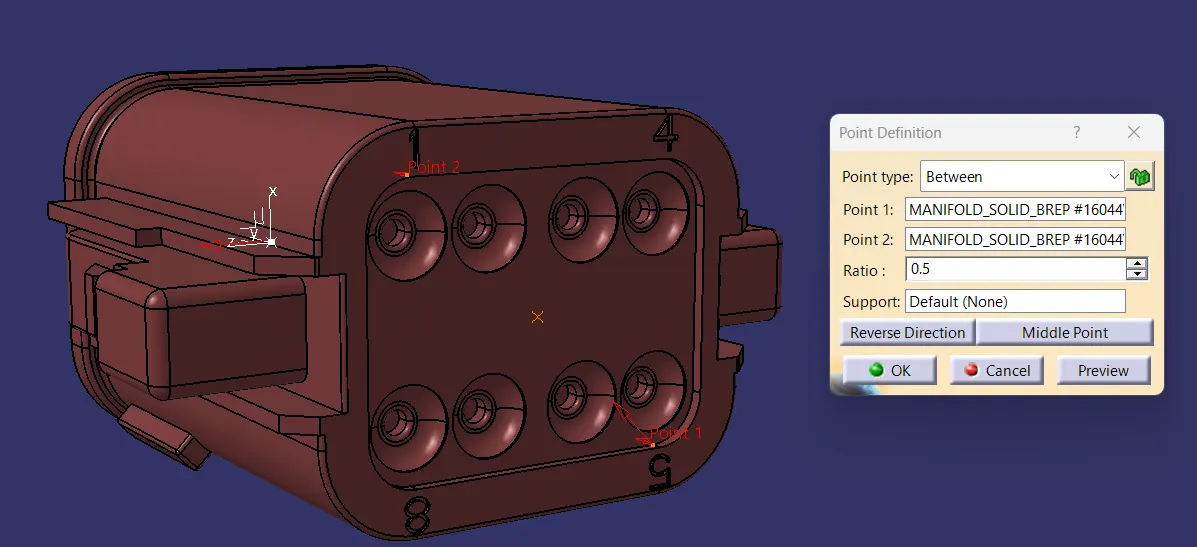
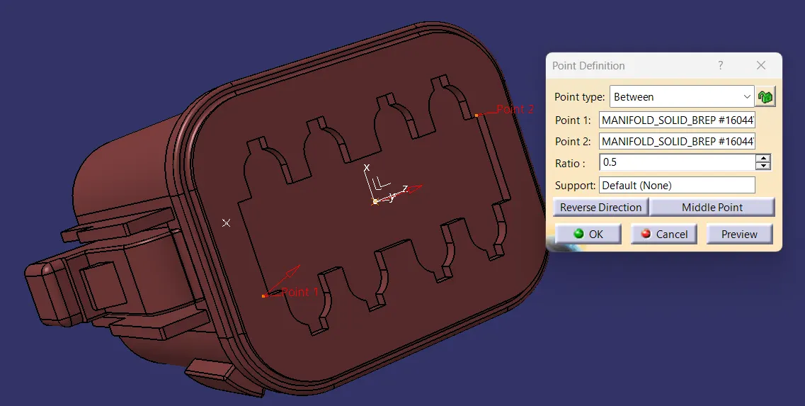
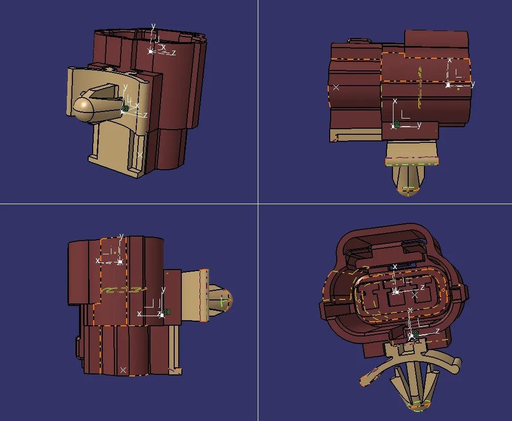
- Then we have to put the axis system on the created points of the connectors with same orientation to ensure the correct assembly of the components.
- Defining the part as connector using the define connector command by selecting the command and selecting the component.
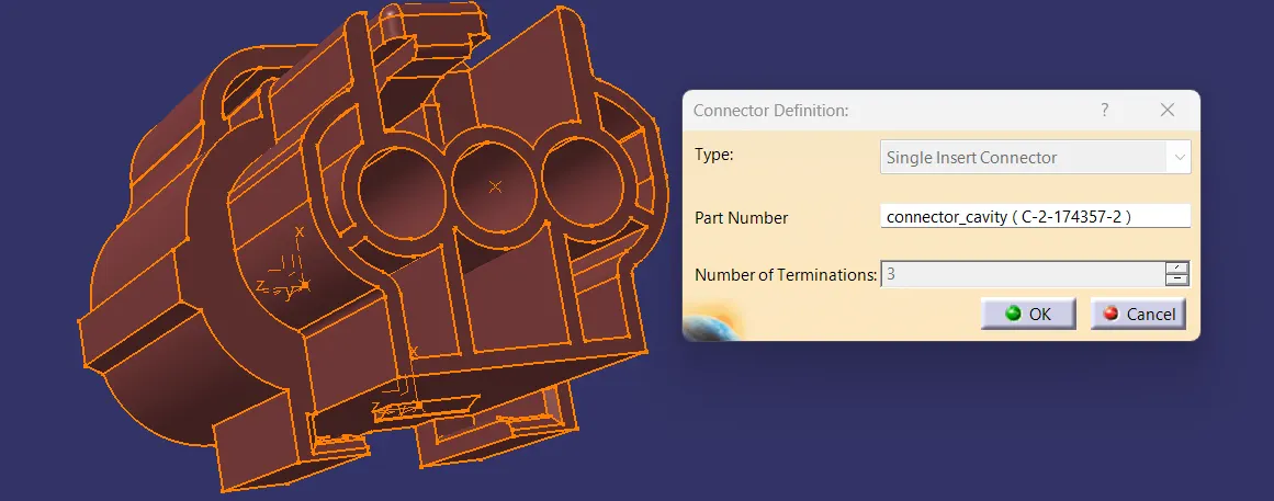
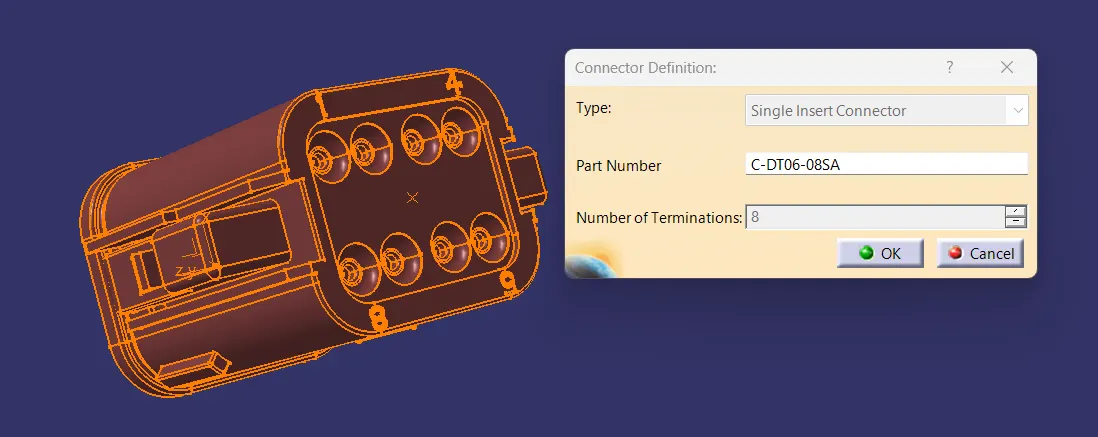
- Define bundle connection point and selecting the required input from the created geometries such as axis and points and face.
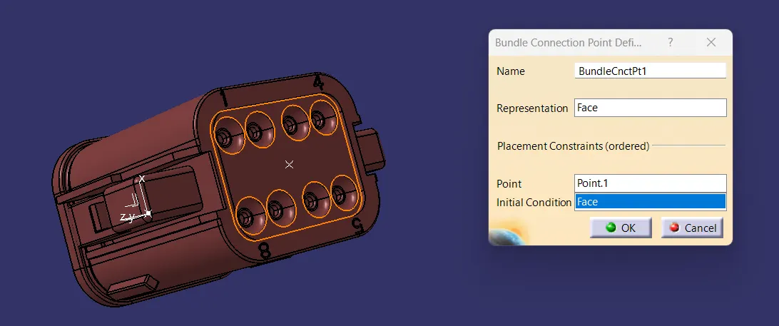
- Define the connector connection point and select the required geometry inputs for connector connection.
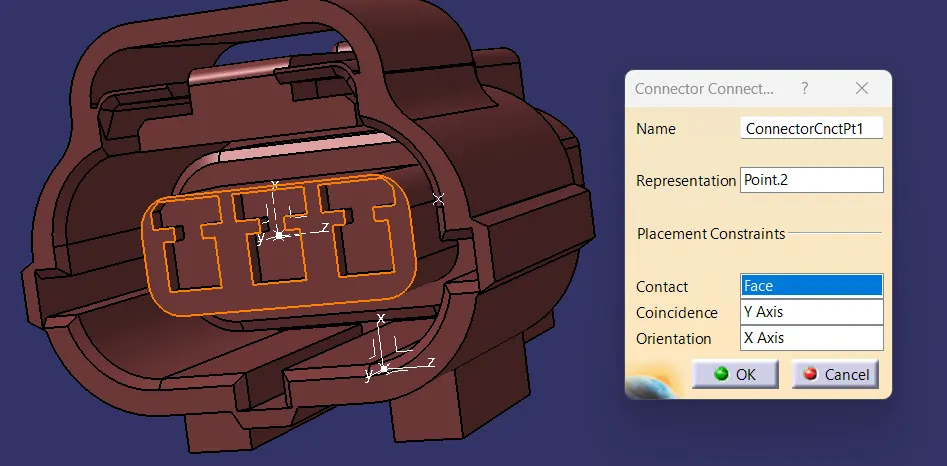
- Then finally we have to define the cavity connection point, here the cavity connection point is only required when there is provision for the mounting clip is given.
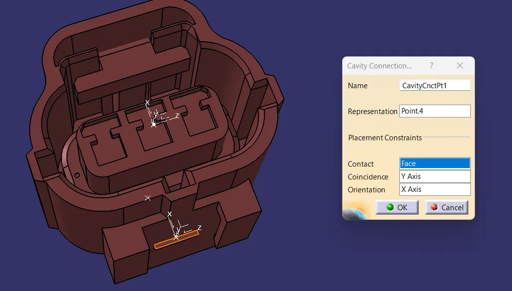
- After defining the connectors, we need to define the clip also, defining the clip also has various step in it.
- For clip we need to define it as mounting component, and select the required input needed for defining it as a mounting component.
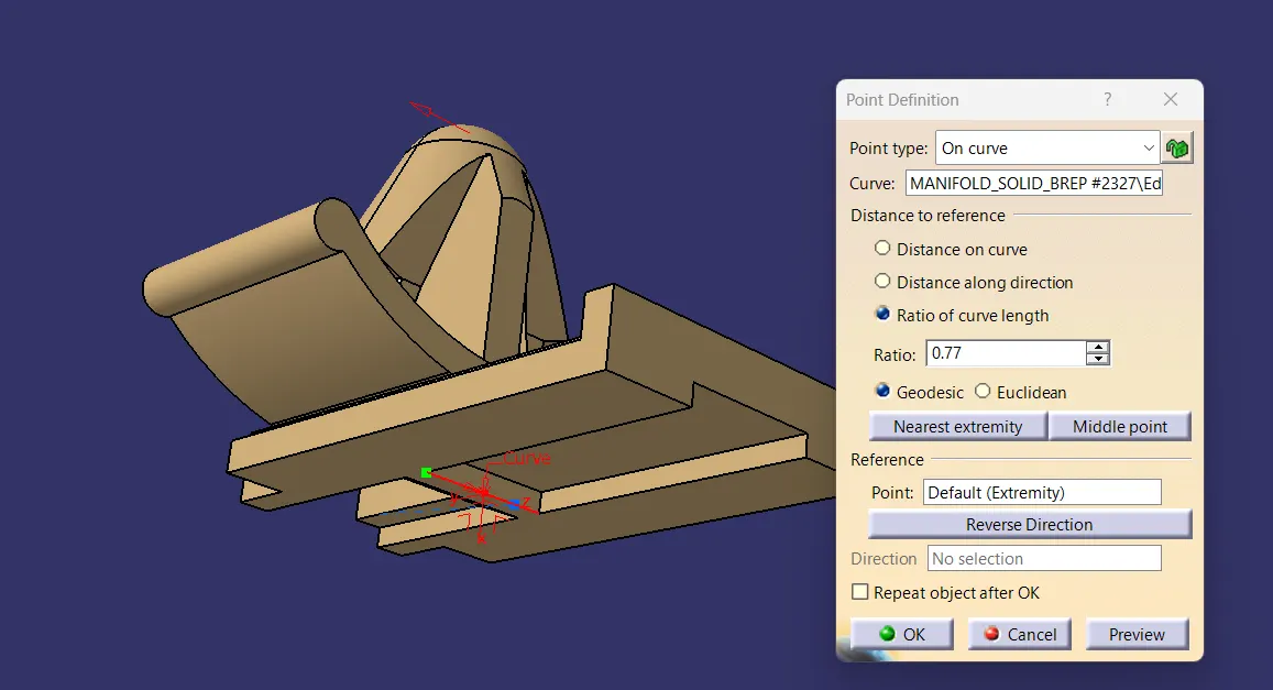
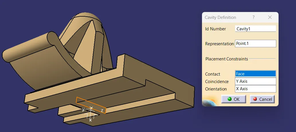
Electrical assembly workbench:
- Open the electrical assembly design workbench by copying and pasting them or by adding the existing component command available in the insert toolbar.
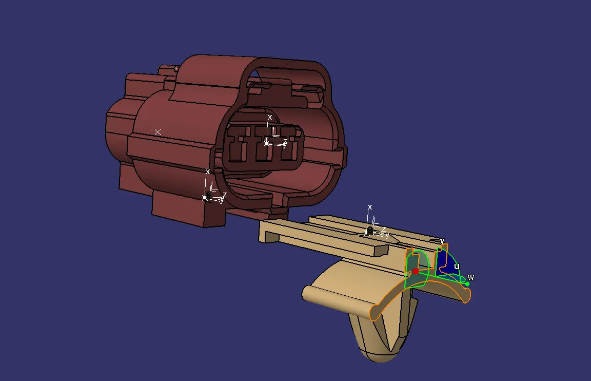
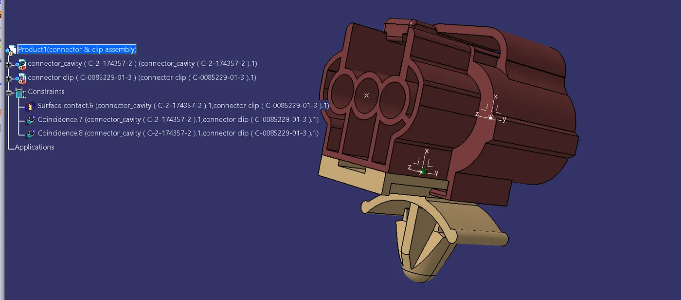
- By using connect electrical devices tool we can join them together by adjusting them to the appropriate location. Here the given connector parts are not compatible with each other so we have assembled the cavity clip and one part of the compatible connector . And the final product is shown below.