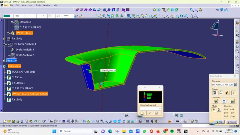
Week 9 - Challenge 2 - Switch Bezel Design
DRAFT ANALYSIS :
our part model created in CAD is used in that technique to analyze if it is manufacturable based on the draft condition used.
DRAFT:
draft is providing angle or tapers on product features such as walls,ribs,posts and bosses that lie parallel to the direction of release from the mold eases part ejection. so draft analysis is used to check these drfts
use the following steps to perfom draft analysis;
step 1: to check the connectivity of the class A surface.
Ensure that there is no gap between the component.
step 2: Find the toling axis of the component.The tooling axis is defines the direction of mould pulls part(core and cavity).
Check visually which is the best possible tooling direction.
check all the 3 axis.
Along x and y is not possible.
Z is the best possible tooling axis.
Create a tooling axis along x and y.
Intersect the zx plane with the fan component. As the result get 2 line of zx plane.
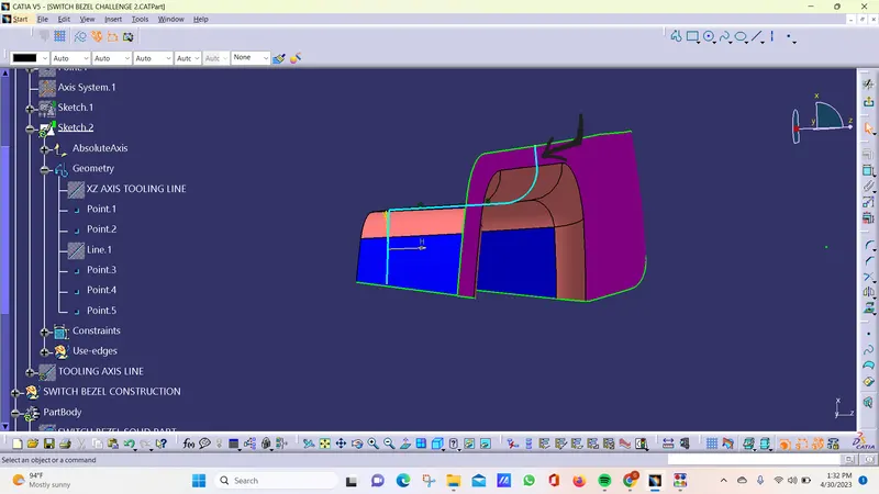
Draw a line along z direction to help visulation to create a dummy tooling line axis.
Ater that created the tooling clearing X direction.
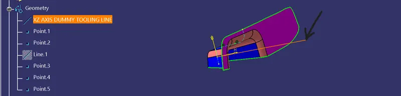
Next need to create along z direction for the tooling clearing Y direction.
same procedure for the other side.
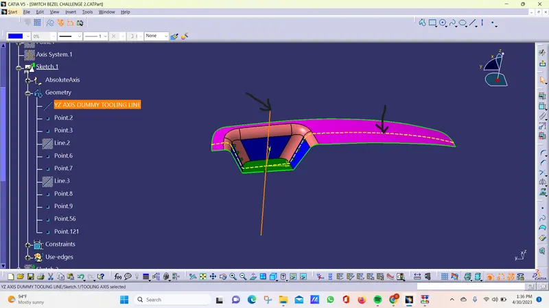
Bisecting lines were used to get the exact medium from the two sides so that maximum positive draft angle can be achieved.
Finally by using the bisecting line option the tooling axis were created by selecting the tooling axis x direction and y direction axis.
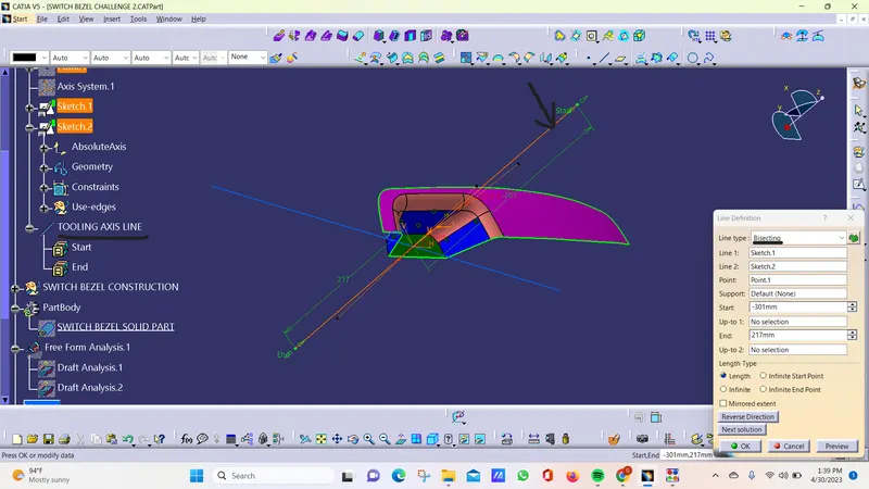
step 3: publication. insert---publication
the tooling axis and class-A surface were published for further easy reference, from Tools – Publications
step 4: Draft analysis tool. Insert--- analysis----featured draft analysis.
Near to isometric tool. CUSTOMIZE VIEW PARAMETER. in the shading click or enable the material box. and click ok.
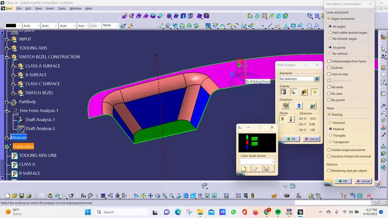
now this is the draft analyst tool.
And next place the axis and lock it.
It displayed in green color.
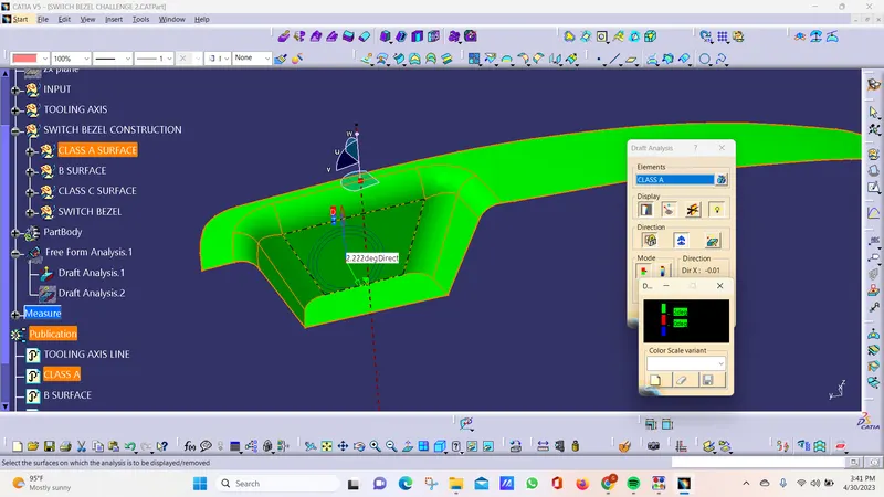
more than 3 is green
red is below 0 deg
blue is 0-3 deg